

Procedural Raytracer
Updated: 30 Jan 2026
Renders a procedural system as a raytraced surface.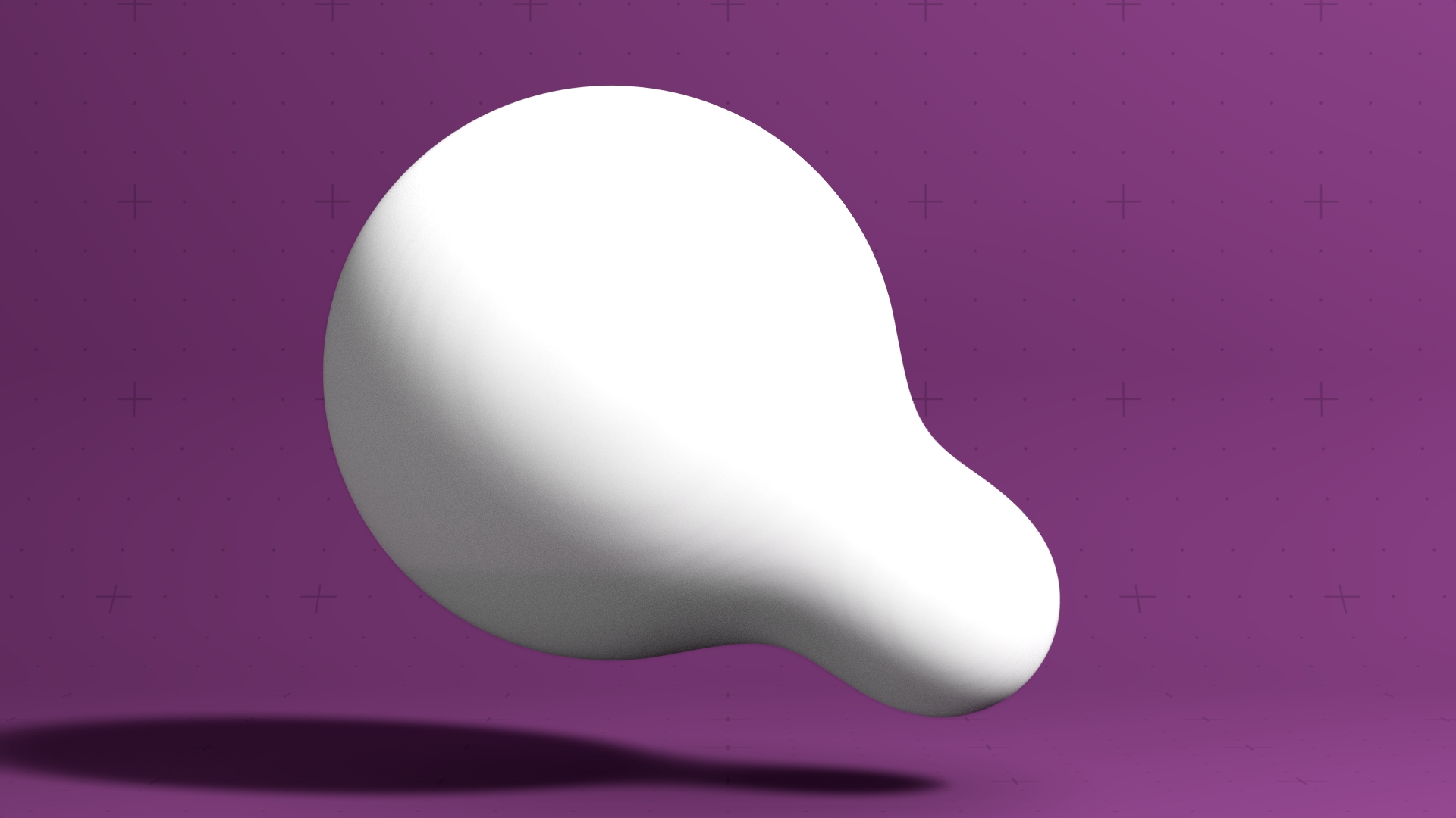
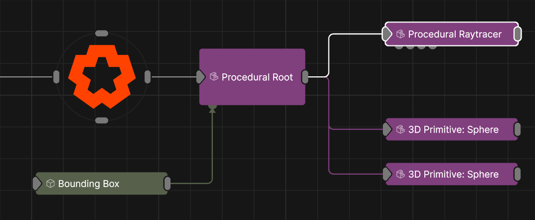
Updated: 30 Jan 2026
Renders a procedural system as a raytraced surface.
This node renders a procedural system as a raytraced surface using ray marching, allowing for significantly more detail and complexity to be rendered.
Ray Marching is a technique for rendering signed distance fields (SDFs) by drawing a ray from the camera and stepping through the SDF using the step size. If the distance to the closest surface (which easily calculable using an SDF) is lower than the step distance, then we know the surface has be hit and the system can be calculated. If the step size is too high, the ray can pass through surfaces it should hit, or hit surfaces it should miss. Lowering the step size can improve this, but can heavily impact perfomance. Complexity of the procedural system can also impact the surface detail, so simplifying the procedural where possible can also improve both accuracy and performance.
The Volumetric mode is a great way to generate clouds, and supports Field Materials.
These properties control the 3D transforms of the node. Transforms will generally be inherited by child nodes, although they can be ignored through the Inherit Transform Channels attributes.
| Parameter | Details |
|---|---|
| Position X | The objects position along the local x-axis. |
| Position Y | The objects position along the local y-axis. |
| Position Z | The objects position along the local z-axis. |
| Rotation Heading | The objects rotation around the local y-axis. |
| Rotation Pitch | The objects rotation around the local x-axis. |
| Rotation Bank | The objects rotation around the local z-axis. |
| Scale X | The objects scale along the local x-axis. |
| Scale Y | The objects scale along the local y-axis. |
| Scale Z | The objects scale along the local z-axis. |
Control the inheritance of the transforms from the parent.
| Parameter | Details |
|---|---|
| Position | Toggle inheritance of the Position from the parent. |
| Rotation | Toggle inheritance of the Rotation from the parent. |
| Scale | Toggle inheritance of the Scale from the parent. |
| World Position Only | Inherit the world position from the parent only, rotation and scale will be ignored. Overrides above properties. |
| Inherit Time | Toggle inheritance of time from the parent. |
These properties control the core behaviours of the node.
| Parameter | Details |
|---|---|
| Render Mode |
Control how the procedural is rendered after being traced.
|
| Step Size | How far the raytracer steps each iteration while finding the surface of the procedural. |
| Hardness | Reduces the emission rate around the edges of the emission area to create softer looking edges. |
| Bounds Size | Sets an outer bound for the volumetrics. Lower values can improve performance and limit the expansion of the procedural, while higher values may lose quality and impact performance - but allows for massive procedural systems to be rendered. |
| Visible | Control whether the node is visible or not to the scene. |
| Parameter | Details |
|---|---|
| Preview in Viewport | Toggle a preview of the Material on a sphere in the Viewport. |
| Parameter | Details |
|---|---|
| Colour | The colour of the material. |
| Brightness | The brightness of the material. |
| Specular Intensity | The intensity of the specular reflection. |
| Specular Colour | The colour of the specular reflection. |
| Colour Map -> Specular Colour | Use the input colour map as the specular reflection colour. |
| Specular Anisotropy | Controls the anisotropy of the specular reflection. |
| Specular Falloff | Controls the falloff of the specular reflection. |
| Diffuse Fresnel | Controls the fresnel effect on the diffuse reflection. |
| Metallicness | Controls the metallicness of the material. |
| Roughness | Controls the roughness of the material. |
| Normal Map Mode |
Changes the format of the input normal map.
|
| Normal Map Intensity | TODO |
| Invert Normals | Flip the normals of each face, so the lighting is tested against the inside face. |
| Emissiveness | How much of a glow is emitted around the object. |
| Emissive Scattering | Controls how much Emissive lighting is scattered in the scene. |
| Emissive Lights Scene | Controls how much Emissive lighting contributes to lighting the scene. |
| Use Displacement |
Enables the use of displacement mapping for the material. *Requires an input displacement map.
|
| Displacement | How much the deformer displaces the original mesh. |
| Displacement Offset | Adds an initial offset to the displacement. |
| Displacement - Use Polygon UVs | TODO |
| Opacity Mode |
Controls the opacity mode of the material, and how it blends with the scene.
|
| Alpha | Set the alpha amount of the material |
| Blend Mode |
Change how the material once added to an object blends with the scene. Only functions with Alpha Mode for details.
|
| Alpha Sort Bias | Biases the alpha sort in order to make it render in front or behind other transparent objects. |
| Output Alpha In GBuffer Composite | Sends the alpha to the gbuffer composite pass. |
| Translucency |
Controls the translucency mode of the material.
|
| Refraction IOR | TODO |
| Aberration | TODO |
| Absorption | How much light is absorbed by the material as light passes through it. |
| Absorption Colour | Colour to use for absorption. |
| Subsurface Weight | Weight of the subsurface scattering effect. |
| Subsurface Scatter Radius | Radius of the subsurface scattering effect. |
| Diffuse Coat | TODO |
| Diffuse Lightmap |
Enables an input diffuse lightmap for the material.
|
| Baked Diffuse Intensity | TODO |
| Ambient Occlusion |
Enables the input ambient occlusion map of the material.
|
| Parameter | Details |
|---|---|
| Colour Texture | Defines the base color of the material’s surface. It represents the surface color under neutral, uniform lighting. |
| Diffuse Map | Specifies the color of light that scatters off the surface in all directions. It is functionally similar to the Colour Texture and is a core component of a material’s appearance. |
| Specular Map | Controls the color and intensity of shiny reflections (specular highlights). Brighter areas on the map indicate a more reflective and shinier surface. |
| Emissiveness Map | Determines which parts of a material appear to glow or emit their own light. Brighter values cause the surface to act as a light source. |
| Metallicness Map | A grayscale map to define how ‘metal-like’ a surface is. White values represent pure metal, while black values represent non-metals. |
| Roughness Map | A grayscale map that controls the roughness of the surface. Black represents a smooth, mirror-like surface with sharp reflections, while white represents a rough surface with blurry, diffuse reflections. |
| Normal Map | Adds surface detail like bumps and scratches without adding more polygons to the model. It simulates how light would interact with a more complex surface, creating the illusion of depth. |
| Displacement Map | Physically displaces the vertices of the model’s geometry based on the map’s values. Unlike a Normal Map, this creates real geometric detail that affects the model’s silhouette. |
| Alpha Map | A grayscale map that controls the transparency of the material. Black areas are fully transparent, white areas are fully opaque, and gray values create semi-transparency. |
| Ambient Occlusion Map | Adds subtle, soft shadows to areas that are occluded from ambient light, such as creases and crevices. This enhances realism and adds perceived depth to the model. |
| Subsurface Colour Map | Defines the color of light after it has scattered beneath the surface of a translucent material, such as skin, wax, or marble. |
| Subsurface Weight Map | Controls the intensity of the subsurface scattering effect across the material, defining how much light penetrates and scatters within the surface. |
| UV Texture Filter Mode |
Determines the algorithm used for sampling texture pixels when viewed at different angles and distances.
|
| Diffuse Map -> AO | A setting to use the Diffuse or Colour map to contribute to the Ambient Occlusion calculation, often darkening areas based on the base color. |
| Texture Mip Bias | An offset that adjusts which mipmap level is used for a texture. Negative values can sharpen distant textures, while positive values can blur them. |
| Parameter | Details |
|---|---|
| Colour Texture UV |
Select the UV for the Colour Texture.
|
| Diffuse Map UV |
Select the UV for the Diffuse Map Texture.
|
| Specular Map UV |
Select the UV for the Specular Map Texture.
|
| Emissiveness Map UV |
Select the UV for the Emissiveness Map Texture.
|
| Metallicness Map UV |
Select the UV for the Metallicness Map Texture.
|
| Roughness Map UV |
Select the UV for the Roughness Map Texture.
|
| Normal Map UV |
Select the UV for the CoNormal Map Texture.
|
| Displacement Map UV |
Select the UV for the Displacement Map Texture.
|
| Alpha Map UV |
Select the UV for the Alpha Map Texture.
|
| Ambient Occlusion Map UV |
Select the UV for the Ambient Occlusion Map Texture.
|
| Subsurface Colour Map UV |
Select the UV for the Subsurface Colour Texture.
|
| Subsurface Weight Map UV |
Select the UV for the Subsurface Weight Texture.
|
| UV Scale X | Scale the UV texture along the X axis. |
| UV Scale Y | Scale the UV texture along the Y axis. |
| UV Offset X | Offset the UV texture along the X axis. |
| UV Offset Y | Offset the UV texture along the Y axis. |
| Diffuse UV Scale X | Scale the Diffuse UV texture along the X axis. |
| Diffuse UV Scale Y | Scale the Diffuse UV texture along the Y axis. |
| Diffuse UV Offset X | Offset the Diffuse UV texture along the X axis. |
| Diffuse UV Offset Y | Offset the Diffuse UV texture along the Y axis. |
| Texture Wrap Mode U |
Controls how textures used by the material are wrapped when the U value range exceeds 0 to 1.
|
| Texture Wrap Mode V |
Controls how textures used by the material are wrapped when the V value range exceeds 0 to 1.
|
| Diffuse Texture Filter Mode |
Controls how textures used by the material are filtered.
|
| Diffuse Texture Wrap Mode U |
Controls how textures used by the material are wrapped when the U value range exceeds 0 to 1.
|
| Diffuse Texture Wrap Mode V |
Controls how textures used by the material are wrapped when the V value range exceeds 0 to 1.
|
| UV Remap Filtering | Enables filtering for remapping UV’s. Only functions with eligible textures. |
| Parameter | Details |
|---|---|
| Lit | Determines if the material is affected by lights in the scene. When disabled, the material appears fully lit by its own colour and texture, regardless of scene lighting. |
| Reflections Mode |
Controls how the material generates reflections from its surroundings.
|
| Shadows |
Defines how the object interacts with shadows in the scene.
|
| Shadow Catcher Colour | Set the colour of the material when “Shadows” is set to “Shadow Catcher”. |
| Render Visibility |
Controls the object’s visibility to different types of rays in the renderer, which is useful for advanced effects.
|
| Raytracing Settings |
Determines whether the material uses the scene’s global raytracing depth settings or custom values.
|
| Max. Diffuse Depth | Limits the number of times a ray can bounce off diffuse surfaces, affecting indirect lighting quality. |
| Max. Glossy Depth | Limits the number of times a ray can reflect off glossy or specular surfaces. |
| Max. Refraction Depth | Limits the number of times a ray can pass through refractive (transparent) surfaces. |
| Parameter | Details |
|---|---|
| Polygon Sidedness |
The orientation of the polygon’s faces.
|
| Flip Polygons | Flips the orientation of the polygon’s faces. |
| Smoothing Angle | The angle difference used to determine a hard edge or a soft curve. |
| Wireframe | Displays the material’s geometry as a wireframe. |
| Parameter | Details |
|---|---|
| Rim Lighting |
Simulates Rim Lighting on the material with respect to the camera.
|
| Rim Lighting Use Material Colour | TODO |
| Rim Lighting Colour | TODO |
| Rim Lighting Intensity | TODO |
| Rim Lighting Falloff | TODO |
| Glow | Controls the glow of the Rim Lighting. |
| Parameter | Details |
|---|---|
| Vertex Colours - Apply To Colour |
Set how the vertex colours apply to the colour of the mesh.
|
| Vertex Colours - Apply To Alpha |
Set how the vertex colours apply to the alpha of the mesh.
|
| Vertex Colours - Apply To Roughness |
Set how the vertex colours apply to the roughness of the mesh.
|
| Vertex Colours - Apply To Metallicness |
Set how the vertex colours apply to the metallicness of the mesh.
|
| Vertex Colours - Apply To Emissiveness |
Set how the vertex colours apply to the emissiveness of the mesh.
|
The properties control the time at which the node is active. See Timeline for editing time segments.
| Parameter | Details |
|---|---|
| Duration |
Control the duration of the node’s time segment.
|
| Node Time | The custom start and end time for the node. |
| Duration (Timecode) | The length of the node’s time segment (in time). |
| Duration (Frames) | The length of the node’s time segment (in frames). |
| Time Segment Enabled | Set whether the node’s time segment is enabled or not in the Timeline. |
| Name | Description | Typical Input |
|---|---|---|
| Material | Override the default material with a material node. | Material |
| Affecting Lights | Lights that will be used in the raytracer. | Light |
| Excluded Lights | Lights that will be excluded from the raytracer. | Light |
| Colour Texture | Input Colour Texture Map | Video Loader |
| Diffuse Texture | Input Diffuse Texture Map | Video Loader |
| Specular Map | Texture applied spatially to the object that defines its specular. | Video Loader |
| Emissiveness Map | Texture applied spatially the object that defines its emissiveness. | Video Loader |
| Metallicness Map | Greysacle texture applied spatially to the object that defines its metallicness. | Video Loader |
| Roughness Map | Greyscale texture applied spatially to the object that defines its roughness. | Video Loader |
| Normal Map | Texture applied spatially to the object that defines its normals. | Generate Normal Map |
| Displacement Map | Texture applied spatially to the object that displaces the vertices of the model’s geometry. | Video Loader |
| Alpha Map | Texture applied spatially to the object that defines its transparency. | Video Loader |
| Ambient Occlusion Map | Texture applied spatially to the object that defines its ambient occlusion. | Video Loader |
| Subsurface Colour Map | Texture applied spatially to the object that defines its subsurface colour. | Video Loader |
| Subsurface Weight Map | Texture that controls the intensity of the subsurface scattering effect. | Video Loader |
| Composite Nodes | Use shader nodes to override the compositing stage of the shader pipeline. | Channel Sampler |
| Mapping | Control how the image input is mapped onto the mesh for displacement. | Mapping |
| Bounding Box | Limit the area for which shadow casting will be calculated. | Bounding Box |
| Transform Modifiers | Apply the transforms of another node to this node. | Null |
| Target Node | Modifiy the rotations of the node to always direct the z axis towards the input. | Null |
| Local Transform Override | Apply the transforms of another node to this node, relative to its parent. | Null |
| Parameter Value Array | Used to set the parameters of the node using an array. | Parameter Array |