

Line Connection Renderer
Updated: 15 Sep 2026
Renders lines between nearby particles.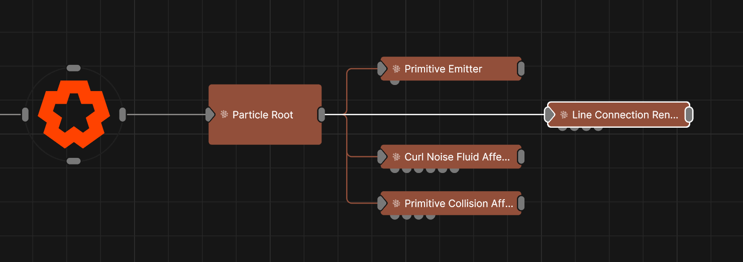
Updated: 15 Sep 2026
Renders lines between nearby particles.
This node renders lines between pairs of nearby particles, giving the impression of a mesh-like structure. The connection pairs are determined by locating particles that are near to each other using a spatial grid. This grid may be scaled by connecting a node to the Bounding Box input, changing the spawning behaviour and potentially affecting performance. Once connected, particles remain joined by a line for a period of time unless one of the particles dies.
These properties control the core behaviours of the node.
| Parameter | Details |
|---|---|
| Geometry Type |
How the lines are generated.
|
| Particle Alpha | Change the alpha value for the particles. |
| Luminance Randomness | Control how much randomness is in the luminance of the rendered particles. |
| Sort Key Value | Biases the depth-based render order, to force the particle system to be drawn before or after other objects in the scene. |
| Depth Bias | Offsets particles in depth so they are closer or further away from the camera, changing the point at which they intersect with the rest of the scene. |
| Distance Threshold | Maximum distance a line can be drawn at. |
| Min Distance Threshold | Maximum distance a line can be drawn at. |
| Particle Use Amount | Percentage of particles that can be used by the node. |
| Line Thickness | Edit the thickness of the line rendered. Only functions if “Use Thick Lines” is enabled. |
| Depth Of Field Amount | How much depth of field effects the particles. |
| Line Connection Lifetime | Length of time a line between two points can exist. |
| Affected Radius | The radius of the area of space within which connections may be generated. |
| Max X Difference | The maximum separation of particles in the X axis that can be connected. |
| Max Y Difference | The maximum separation of particles in the Y axis that can be connected. |
| Max Z Difference | The maximum separation of particles in the Z axis that can be connected. |
| Cast Shadows | Control whether shadows are cast. |
| Sort Particles | Toggle whether the particles are sorted by depth from camera from back to front before rendering, enabling transparent particles to be rendered correctly. |
| Blend Mode | Edit the blend mode used for the particles. See Blend Modes for details. |
| Max Lines Per Particle | Maximum number of lines that can be drawn from each particle. |
| Use Locality Grid | TBC. |
| Parameter | Details |
|---|---|
| Preview in Viewport | Toggle a preview of the Material on a sphere in the Viewport. |
| Parameter | Details |
|---|---|
| Material Mode |
The render mode for the blended material: Solid, Transparent, SSS, or Wireframe.
|
| Colour | The colour of the material. |
| Brightness | The brightness of the material. |
| Specular Intensity | The intensity of the specular reflection. |
| Specular Colour | The colour of the specular reflection. |
| Colour Map -> Specular Colour | Use the input colour map as the specular reflection colour. |
| Specular Anisotropy | Controls the anisotropy of the specular reflection. |
| Specular Falloff | Controls the falloff of the specular reflection. |
| Diffuse Fresnel | Controls the fresnel effect on the diffuse reflection. |
| Metallicness | Controls the metallicness of the material. |
| Roughness | Controls the roughness of the material. |
| Normal Map Mode |
Changes the format of the input normal map.
|
| Normal Map Intensity | TODO |
| Normal Map - Invert Normal X | Flips the red channel of the normal map, mirroring normals along X for maps authored with a different handedness. |
| Normal Map - Invert Normal Y | Flips the green channel of the normal map, mirroring normals along Y for maps authored with a different handedness. |
| Normal Map - Invert Normal Z | Flips the blue channel of the normal map, mirroring normals along Z for maps authored with a different handedness. |
| Invert Normals | Flip the normals of each face, so the lighting is tested against the inside face. |
| Emissiveness | How much of a glow is emitted around the object. |
| Emissive Scattering | Controls how much Emissive lighting is scattered in the scene. |
| Emissive Lights Scene | Controls how much Emissive lighting contributes to lighting the scene. |
| Use Displacement |
Enables the use of displacement mapping for the material. *Requires an input displacement map.
|
| Displacement | How much the deformer displaces the original mesh. |
| Displacement Offset | Adds an initial offset to the displacement. |
| Parallax Amount | How strongly the height map shifts surface sampling to suggest depth (parallax occlusion). |
| Displacement - Use Polygon UVs | TODO |
| Displacement - Fix Tessellation Seams | Welds UV-shell borders during displacement so tessellated seams do not open up along UV islands. |
| Opacity Mode |
Controls the opacity mode of the material, and how it blends with the scene.
|
| Alpha | Set the alpha amount of the material |
| Blend Mode |
Change how the material once added to an object blends with the scene. Only functions with Alpha Mode for details.
|
| Alpha Sort Bias | Biases the alpha sort in order to make it render in front or behind other transparent objects. |
| Output Alpha In GBuffer Composite | Sends the alpha to the gbuffer composite pass. |
| Refractions Mode |
Whether the blended material refracts rays: Full Refractions or Off.
|
| Translucency |
Controls the translucency mode of the material.
|
| Refraction IOR | TODO |
| Aberration | TODO |
| Absorption | How much light is absorbed by the material as light passes through it. |
| Absorption Colour | Colour to use for absorption. |
| Subsurface Weight | Weight of the subsurface scattering effect. |
| Subsurface Scatter Radius | Radius of the subsurface scattering effect. |
| Density | The density, for use in some simulations. |
| Diffuse Coat | TODO |
| Diffuse Lightmap |
Enables an input diffuse lightmap for the material.
|
| Baked Diffuse Intensity | TODO |
| Ambient Occlusion |
Enables the input ambient occlusion map of the material.
|
| Parameter | Details |
|---|---|
| Colour Texture | Defines the base color of the material’s surface. It represents the surface color under neutral, uniform lighting. |
| Diffuse Map | Specifies the color of light that scatters off the surface in all directions. It is functionally similar to the Colour Texture and is a core component of a material’s appearance. |
| Specular Map | Controls the color and intensity of shiny reflections (specular highlights). Brighter areas on the map indicate a more reflective and shinier surface. |
| Emissiveness Map | Determines which parts of a material appear to glow or emit their own light. Brighter values cause the surface to act as a light source. |
| Metallicness Map | A grayscale map to define how ‘metal-like’ a surface is. White values represent pure metal, while black values represent non-metals. |
| Roughness Map | A grayscale map that controls the roughness of the surface. Black represents a smooth, mirror-like surface with sharp reflections, while white represents a rough surface with blurry, diffuse reflections. |
| Normal Map | Adds surface detail like bumps and scratches without adding more polygons to the model. It simulates how light would interact with a more complex surface, creating the illusion of depth. |
| Displacement Map | Physically displaces the vertices of the model’s geometry based on the map’s values. Unlike a Normal Map, this creates real geometric detail that affects the model’s silhouette. |
| Alpha Map | A grayscale map that controls the transparency of the material. Black areas are fully transparent, white areas are fully opaque, and gray values create semi-transparency. |
| Ambient Occlusion Map | Adds subtle, soft shadows to areas that are occluded from ambient light, such as creases and crevices. This enhances realism and adds perceived depth to the model. |
| Subsurface Colour Map | Defines the color of light after it has scattered beneath the surface of a translucent material, such as skin, wax, or marble. |
| Subsurface Weight Map | Controls the intensity of the subsurface scattering effect across the material, defining how much light penetrates and scatters within the surface. |
| UV Texture Filter Mode |
Determines the algorithm used for sampling texture pixels when viewed at different angles and distances.
|
| Diffuse Map -> AO | A setting to use the Diffuse or Colour map to contribute to the Ambient Occlusion calculation, often darkening areas based on the base color. |
| Texture Mip Bias | An offset that adjusts which mipmap level is used for a texture. Negative values can sharpen distant textures, while positive values can blur them. |
| Parameter | Details |
|---|---|
| Colour Texture UV |
Select the UV for the Colour Texture.
|
| Diffuse Map UV |
Select the UV for the Diffuse Map Texture.
|
| Specular Map UV |
Select the UV for the Specular Map Texture.
|
| Emissiveness Map UV |
Select the UV for the Emissiveness Map Texture.
|
| Metallicness Map UV |
Select the UV for the Metallicness Map Texture.
|
| Roughness Map UV |
Select the UV for the Roughness Map Texture.
|
| Normal Map UV |
Select the UV for the CoNormal Map Texture.
|
| Displacement Map UV |
Select the UV for the Displacement Map Texture.
|
| Alpha Map UV |
Select the UV for the Alpha Map Texture.
|
| Ambient Occlusion Map UV |
Select the UV for the Ambient Occlusion Map Texture.
|
| Subsurface Colour Map UV |
Select the UV for the Subsurface Colour Texture.
|
| Subsurface Weight Map UV |
Select the UV for the Subsurface Weight Texture.
|
| UV Scale X | Scale the UV texture along the X axis. |
| UV Scale Y | Scale the UV texture along the Y axis. |
| UV Offset X | Offset the UV texture along the X axis. |
| UV Offset Y | Offset the UV texture along the Y axis. |
| Diffuse UV Scale X | Scale the Diffuse UV texture along the X axis. |
| Diffuse UV Scale Y | Scale the Diffuse UV texture along the Y axis. |
| Diffuse UV Offset X | Offset the Diffuse UV texture along the X axis. |
| Diffuse UV Offset Y | Offset the Diffuse UV texture along the Y axis. |
| Texture Wrap Mode U |
Controls how textures used by the material are wrapped when the U value range exceeds 0 to 1.
|
| Texture Wrap Mode V |
Controls how textures used by the material are wrapped when the V value range exceeds 0 to 1.
|
| Diffuse Texture Filter Mode |
Controls how textures used by the material are filtered.
|
| Diffuse Texture Wrap Mode U |
Controls how textures used by the material are wrapped when the U value range exceeds 0 to 1.
|
| Diffuse Texture Wrap Mode V |
Controls how textures used by the material are wrapped when the V value range exceeds 0 to 1.
|
| UV Remap Filtering | Enables filtering for remapping UV’s. Only functions with eligible textures. |
| Parameter | Details |
|---|---|
| Lit |
Determines if the material is affected by lights in the scene. When disabled, the material appears fully lit by its own colour and texture, regardless of scene lighting.
|
| Reflections Mode |
Controls how the material generates reflections from its surroundings.
|
| Shadows |
Defines how the object interacts with shadows in the scene.
|
| Shadow Catcher Colour | Set the colour of the material when “Shadows” is set to “Shadow Catcher”. |
| Raytraced | Include the blended material in raytraced reflections and refractions. |
| Voxel Cone | Include the blended material in voxel cone traced lighting, so it contributes indirect light and bounces. |
| Screen Space | Include the blended material in screen space reflection and refraction passes. |
| Probes | Include the blended material when baking lighting probes, so it casts indirect light. |
| Environment Mapping | Apply the environment map to the blended material’s reflections. |
| Subsurface Scatter | Include the blended material in subsurface scattering passes, letting light bleed through the surface. |
| Render Visibility |
Controls the object’s visibility to different types of rays in the renderer, which is useful for advanced effects.
|
| Raytracing Settings |
Determines whether the material uses the scene’s global raytracing depth settings or custom values.
|
| Max. Diffuse Depth | Limits the number of times a ray can bounce off diffuse surfaces, affecting indirect lighting quality. |
| Max. Glossy Depth | Limits the number of times a ray can reflect off glossy or specular surfaces. |
| Max. Refraction Depth | Limits the number of times a ray can pass through refractive (transparent) surfaces. |
| Parameter | Details |
|---|---|
| Polygon Sidedness |
The orientation of the polygon’s faces.
|
| Flip Polygons | Flips the orientation of the polygon’s faces. |
| Surface Smoothing |
Smooth the vertex normals of the blended material across edges: Smooth, or Flat.
|
| Normal Smoothness | How strongly normals are smoothed for the blended material, softening faceting between polygons. |
| Smoothing Angle | The angle difference used to determine a hard edge or a soft curve. |
| Wireframe | Displays the material’s geometry as a wireframe. |
| Parameter | Details |
|---|---|
| Rim Lighting |
Simulates Rim Lighting on the material with respect to the camera.
|
| Rim Lighting Use Material Colour | TODO |
| Rim Lighting Colour | TODO |
| Rim Lighting Intensity | TODO |
| Rim Lighting Falloff | TODO |
| Glow | Controls the glow of the Rim Lighting. |
| Parameter | Details |
|---|---|
| Vertex Colours - Apply To Colour |
Set how the vertex colours apply to the colour of the mesh.
|
| Vertex Colours - Apply To Alpha |
Set how the vertex colours apply to the alpha of the mesh.
|
| Vertex Colours - Apply To Roughness |
Set how the vertex colours apply to the roughness of the mesh.
|
| Vertex Colours - Apply To Metallicness |
Set how the vertex colours apply to the metallicness of the mesh.
|
| Vertex Colours - Apply To Emissiveness |
Set how the vertex colours apply to the emissiveness of the mesh.
|
| Flat Shade Colours | Flatten vertex colours across each polygon so the blended material reads solid facets instead of interpolating gradients. |
The properties control the time at which the node is active. See Timeline for editing time segments.
| Parameter | Details |
|---|---|
| Duration |
Control the duration of the node’s time segment.
|
| Node Time | The custom start and end time for the node. |
| Duration (Timecode) | The length of the node’s time segment (in time). |
| Duration (Frames) | The length of the node’s time segment (in frames). |
| Time Segment Enabled | Set whether the node’s time segment is enabled or not in the Timeline. |
| Name | Description | Typical Input |
|---|---|---|
| Bounding Box | Limit the area for which shadow casting will be calculated. | Bounding Box |
| Affected Centre Position | Controls the centre position of a radial area of space where the connections may be generated. | Null |
| Material | Override the default material with a material node. | Materials |
| Rendered Emitters | Specify which emitters are rendered using this renderer. By default, all emitters connected to the same particle root as the renderer are rendered. | Primitive Emitter |
| Transform Modifiers | Apply the transforms of another node to this node. | Null |
| Target Node | Modifiy the rotations of the node to always direct the z axis towards the input. | Null |
| Local Transform Override | Apply the transforms of another node to this node, relative to its parent. | Null |
| Parameter Value Array | Used to set the parameters of the node using an array. | Parameter Array |