Mesh Attractor
Updated: 15 Dec 2025
This node is used to attract or repel particles from the surface of a given 3D object, affect them by the velocity of the mesh, or make them flow along the surface of a mesh.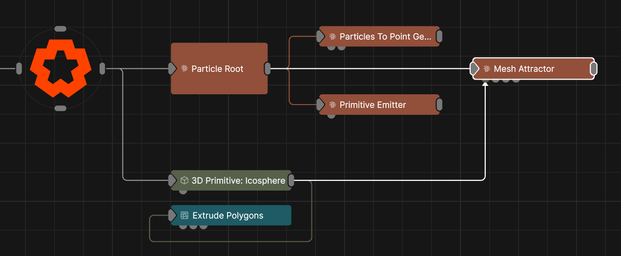
Updated: 15 Dec 2025
This node is used to attract or repel particles from the surface of a given 3D object, affect them by the velocity of the mesh, or make them flow along the surface of a mesh.
This node is used to attract or repel particles from the surface of a given 3D object, affect them by the velocity of the mesh, or make them flow along the surface of a mesh. Particles will use the closest point on the object’s surface to move towards or away from; this may be offset randomly using the Randomness attribute to create a noisier shape.
This node requires a geometry node to be connected via the Object Nodes input.
These properties control the core behaviours of the node.
| Parameter | Details |
|---|---|
| Mode |
The affector mode.
attract, particle are attracted towards the surface of the mesh.
repel, particles are repelled away from the surface of the mesh.
follow surface, particles are attracted to the surface of the mesh and then move across the surface of the mesh once close enough to it.
velocity, particles are affected by the movement of the mesh.
|
| Target Type | Choose where particles move to, mesh polygons or mesh vertices. |
| Radius | Alter the outer radius at which the affector is no longer effective. |
| Randomness | How much randomness is added in the particles movement. |
| Velocity Scale | Scale the strength of the affectors velocity on the particles. |
| Node Velocity Amount | How much of the mesh’s velocity to apply to the particles. |
| Node Velocity Mode |
Which particles to apply velocity to when using ‘Node Velocity Amount’
|
| Weight | How strong an effect has on the particles. |
| Colour Weight | The amount in which the colour of the particles blends towards the target object’s colours. |
| Stickiness | Controls how much the particle sticks to the surface of the shape once it reaches it. |
| Stick To Surface Distance | The distance below which the particle is considered stuck to the surface. |
| Life Effect Coeffs | How much the particles are affected by the affector at different stages of the particles life cycle. Values 1 and 2 are control points used to control a bezier curve between values 0 and 3. |
| Parameter | Details |
|---|---|
| Blend Mode | Choose how the particle colours blend to the source colours. |
These properties are used to set the falloff of the node.
| Parameter | Details |
|---|---|
| Falloff Mode |
Which shape to use to calculate the falloff.
|
| Falloff Axis | Which axis the falloff should be oriented on. |
| Falloff Direction |
When using Planar mode, which directions to use to calculate the falloff.
|
| Falloff Easing Mode |
Interpolation method used to calculate the falloff within its range of influence.
|
| Falloff Size X | Size of the falloff range along the X axis. |
| Falloff Size Y | Size of the falloff range along the Y axis. |
| Falloff Size Z | Size of the falloff range along the Z axis. |
| Outer Range | Outer range of the falloff, outside of which the falloff is no longer effective. |
| Inner Range | Inner range of the falloff, inside of which the falloff is fully effective. |
| Invert | Inverts the effect of the falloff. |
| Curve Power | Controls the rate of change for the falloff between the inner and outer range. |
The properties control the time at which the node is active. See Timeline for editing time segments.
| Parameter | Details |
|---|---|
| Duration |
Control the duration of the node’s time segment.
|
| Node Time | The custom start and end time for the node. |
| Duration (Timecode) | The length of the node’s time segment (in time). |
| Duration (Frames) | The length of the node’s time segment (in frames). |
| Time Segment Enabled | Set whether the node’s time segment is enabled or not in the Timeline. |
| Name | Description | Typical Input |
|---|---|---|
| Falloff Node | Use an input falloff node to override the falloff. | Falloff |
| Object Nodes | The source meshes for the particles ot be attracted to. | 3D Object |
| Affected Emitters | Choose which particle emitters can be affected by the affector. | Primitive Emitter |
| Procedural Falloff | Use the distance field from a procedural system to vary how strong the affector is. | Procedural Root |
| Weights | Add a particle weight node to vary the node’s effect on the particle system. | Noise Weight |
| Transform Modifiers | Apply the transforms of another node to this node. | Null |
| Target Node | Modifiy the rotations of the node to always direct the z axis towards the input. | Null |
| Local Transform Override | Apply the transforms of another node to this node, relative to its parent. | Null |