Primitive Collision Affector
Updated: 18 Feb 2025
Allows particle collisions with simple 3D primitives.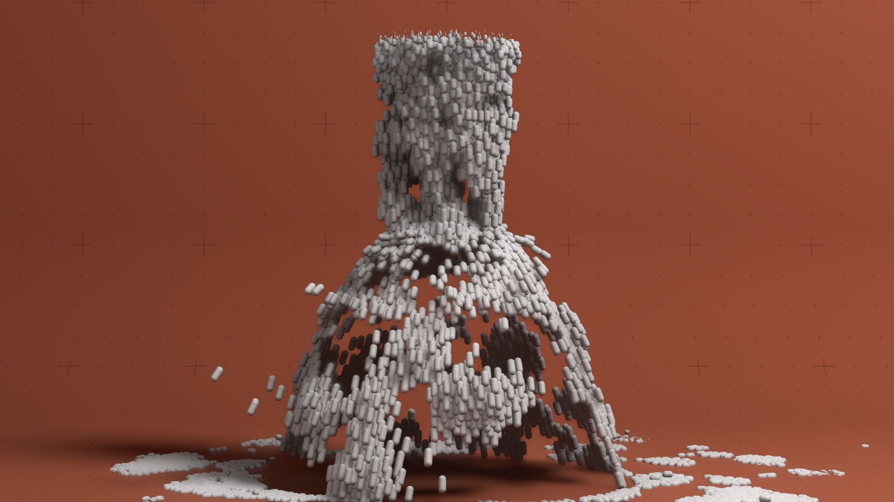
Updated: 18 Feb 2025
Allows particle collisions with simple 3D primitives.
This node simulates collisions between particles and a 3D primitive. It uses ray traced intersections with triangles contained in a bounding volume hierarchy structure. This allows for fast, accurate collisions with 3D primitive, but animating.
Particle Events may be triggered when collisions occur. This allows effects such as particles changing colour, size or material on collision, or emitting new particles at the point of collision.
These properties control the core behaviours of the node.
| Parameter | Details |
|---|---|
| Particle Collision Radius | Radius around a particle in which it will calculate colliding. |
| Collision Velocity Scale | Scales the velocity of the particle after a collision so they can be made to slow down. |
| Primitive Type |
The shape in which the particles are affected.
|
| Inverted | Invert the object so areas inside the mesh are considered hollow and areas outside are filled. |
These properties are used to set the falloff of the node.
| Parameter | Details |
|---|---|
| Falloff Mode |
Which shape to use to calculate the falloff.
|
| Falloff Axis | Which axis the falloff should be oriented on. |
| Falloff Direction |
When using Planar mode, which directions to use to calculate the falloff.
|
| Falloff Easing Mode |
Interpolation method used to calculate the falloff within its range of influence.
|
| Falloff Size X | Size of the falloff range along the X axis. |
| Falloff Size Y | Size of the falloff range along the Y axis. |
| Falloff Size Z | Size of the falloff range along the Z axis. |
| Outer Range | Outer range of the falloff, outside of which the falloff is no longer effective. |
| Inner Range | Inner range of the falloff, inside of which the falloff is fully effective. |
| Invert | Inverts the effect of the falloff. |
| Curve Power | Controls the rate of change for the falloff between the inner and outer range. |
The properties control the time at which the node is active. See Timeline for editing time segments.
| Parameter | Details |
|---|---|
| Duration |
Control the duration of the node’s time segment.
|
| Node Time | The custom start and end time for the node. |
| Duration (Timecode) | The length of the node’s time segment (in time). |
| Duration (Frames) | The length of the node’s time segment (in frames). |
| Time Segment Enabled | Set whether the node’s time segment is enabled or not in the Timeline. |
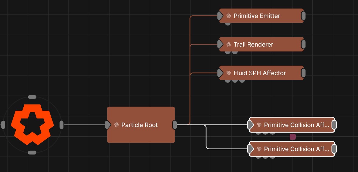
| Name | Description | Typical Input |
|---|---|---|
| Falloff Node | Use an input falloff node to override the falloff. | Falloff |
| Collision Event Nodes | Particle events to be triggered when collisions occur. | Particle Event |
| Affected Emitters | Choose which particle emitters can be affected by the affector. | Primitive Emitter |
| Procedural Falloff | Use the distance field from a procedural system to vary how strong the affector is. | Procedural Root |
| Weights | Add a particle weight node to vary the node’s effect on the particle system. | Noise Weight |
| Transform Modifiers | Apply the transforms of another node to this node. | Null |
| Target Node | Modifiy the rotations of the node to always direct the z axis towards the input. | Null |
| Local Transform Override | Apply the transforms of another node to this node, relative to its parent. | Null |