Points Affector
Updated: 15 Dec 2025
Uses points sources to disturb the particles.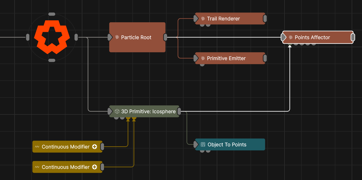
Updated: 15 Dec 2025
Uses points sources to disturb the particles.
This node affects particles by positional vortex forces created around points from another particle system, or vertices of a 3D Object. This can be used to make one particle system “move through” another and appear to affect it.
These properties control the 3D transforms of the node. Transforms will generally be inherited by child nodes, although they can be ignored through the Inherit Transform Channels attributes.
| Parameter | Details |
|---|---|
| Position X | The objects position along the local x-axis. |
| Position Y | The objects position along the local y-axis. |
| Position Z | The objects position along the local z-axis. |
| Rotation Heading | The objects rotation around the local y-axis. |
| Rotation Pitch | The objects rotation around the local x-axis. |
| Rotation Bank | The objects rotation around the local z-axis. |
| Scale X | The objects scale along the local x-axis. |
| Scale Y | The objects scale along the local y-axis. |
| Scale Z | The objects scale along the local z-axis. |
Control the inheritance of the transforms from the parent.
| Parameter | Details |
|---|---|
| Position | Toggle inheritance of the Position from the parent. |
| Rotation | Toggle inheritance of the Rotation from the parent. |
| Scale | Toggle inheritance of the Scale from the parent. |
| World Position Only | Inherit the world position from the parent only, rotation and scale will be ignored. Overrides above properties. |
| Inherit Time | Toggle inheritance of time from the parent. |
These properties control the core behaviours of the node.
| Parameter | Details |
|---|---|
| Velocity Mode |
What type of velocity should be applied.
|
| Velocity Apply Mode |
|
| Velocity Scale | Scale the strength of the affectors velocity on the particles. |
| Point Falloff Distance | The radius of falloff of effect from each point. |
| Point Falloff Power | The sharpness of the falloff from each point. |
| Point Position Randomness | Add random positional offsets from each point to expand its area of influence. |
| Point Position Random Shape |
When applying Point Position Randomness, what shape to apply it in around each point.
|
| Point Selection Mode |
How each particle chooses which point to be affected by.
|
| Randomness | How much randomness is added in the particles movement. |
| Life Effect Coeffs | How much the particles are affected by the affector at different stages of the particles life cycle. Values 1 and 2 are control points used to control a bezier curve between values 0 and 3. |
These properties are used to set the falloff of the node.
| Parameter | Details |
|---|---|
| Falloff Mode |
Which shape to use to calculate the falloff.
|
| Falloff Axis | Which axis the falloff should be oriented on. |
| Falloff Direction |
When using Planar mode, which directions to use to calculate the falloff.
|
| Falloff Easing Mode |
Interpolation method used to calculate the falloff within its range of influence.
|
| Falloff Size X | Size of the falloff range along the X axis. |
| Falloff Size Y | Size of the falloff range along the Y axis. |
| Falloff Size Z | Size of the falloff range along the Z axis. |
| Outer Range | Outer range of the falloff, outside of which the falloff is no longer effective. |
| Inner Range | Inner range of the falloff, inside of which the falloff is fully effective. |
| Invert | Inverts the effect of the falloff. |
| Curve Power | Controls the rate of change for the falloff between the inner and outer range. |
The properties control the time at which the node is active. See Timeline for editing time segments.
| Parameter | Details |
|---|---|
| Duration |
Control the duration of the node’s time segment.
|
| Node Time | The custom start and end time for the node. |
| Duration (Timecode) | The length of the node’s time segment (in time). |
| Duration (Frames) | The length of the node’s time segment (in frames). |
| Time Segment Enabled | Set whether the node’s time segment is enabled or not in the Timeline. |
| Name | Description | Typical Input |
|---|---|---|
| Falloff Node | Use an input falloff node to override the falloff. | Falloff |
| Point Source Node | The source of the point data. | Particle Root Node |
| Mask Node | Mask out areas that particles cannot spawn. | Image Plane |
| Affected Emitters | Choose which particle emitters can be affected by the affector. | Primitive Emitter |
| Procedural Falloff | Use the distance field from a procedural system to vary how strong the affector is. | Procedural Root |
| Weights | Add a particle weight node to vary the node’s effect on the particle system. | Noise Weight |
| Transform Modifiers | Apply the transforms of another node to this node. | Null |
| Target Node | Modifiy the rotations of the node to always direct the z axis towards the input. | Null |
| Local Transform Override | Apply the transforms of another node to this node, relative to its parent. | Null |