Primitive Affector
Updated: 3 Mar 2026
Apply forces to particles from primitive shapes.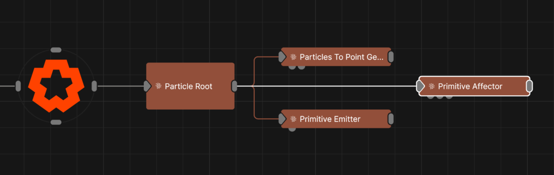
Updated: 3 Mar 2026
Apply forces to particles from primitive shapes.
This node is used to attract or repel particles from the surface of the selected primitive type. This is typically used to make particles form into a given shape. Particles will use the closest point on the primitive’s surface to move towards or away from; this may be offset randomly using the Randomness attribute to create a noisier shape.
All nodes connected to this node are treated as if flowing to the parent node, and inherits any transformation changes along the chain.
These properties control the 3D transforms of the node. Transforms will generally be inherited by child nodes, although they can be ignored through the Inherit Transform Channels attributes.
| Parameter | Details |
|---|---|
| Position X | The objects position along the local x-axis. |
| Position Y | The objects position along the local y-axis. |
| Position Z | The objects position along the local z-axis. |
| Rotation Heading | The objects rotation around the local y-axis. |
| Rotation Pitch | The objects rotation around the local x-axis. |
| Rotation Bank | The objects rotation around the local z-axis. |
| Scale X | The objects scale along the local x-axis. |
| Scale Y | The objects scale along the local y-axis. |
| Scale Z | The objects scale along the local z-axis. |
Control the inheritance of the transforms from the parent.
| Parameter | Details |
|---|---|
| Position | Toggle inheritance of the Position from the parent. |
| Rotation | Toggle inheritance of the Rotation from the parent. |
| Scale | Toggle inheritance of the Scale from the parent. |
| World Position Only | Inherit the world position from the parent only, rotation and scale will be ignored. Overrides above properties. |
| Inherit Time | Toggle inheritance of time from the parent. |
These properties control the core behaviours of the node.
| Parameter | Details |
|---|---|
| Primitive Type |
Choose which primitive shape to use.
|
| Velocity Mode | Control whether the particles should be attracted or repelled by the primitive. |
| Use Colours | Toggle whether to use the colours input by the mesh. |
| Radius | Alter the outer radius at which the affector is no longer effective. |
| Randomness | Applies a random offset to the position the particles move towards or away from. |
| Velocity Randomness | Amount by which the resultant velocity is randomised. |
| Velocity Scale | Scale the strength of the affectors velocity on the particles. |
| Node Velocity Amount | Control how much the affector’s movement influences particle motion. Particles inside or near the surface are moved proportionally, with “Radius” defining a soft falloff range based on distance to the primitive surface. |
| Weight | How strong an effect has on the particles. |
| Colour Weight | Controls how much the colour value generated by the affector is blended with the particle’s current colour. |
| Stickiness | Controls how much the particle sticks to the surface of the shape once it reaches it. |
| Life Effect Coeffs | How much the particles are affected by the affector at different stages of the particles life cycle. Values 1 and 2 are control points used to control a bezier curve between values 0 and 3. |
How the primitive colours are blended with the particle colours.
| Parameter | Details |
|---|---|
| Blend Mode | Change how the particle affector changes with the particles current changes. |
These properties are used to set the falloff of the node.
| Parameter | Details |
|---|---|
| Falloff Mode |
Which shape to use to calculate the falloff.
|
| Falloff Axis | Which axis the falloff should be oriented on. |
| Falloff Direction |
When using Planar mode, which directions to use to calculate the falloff.
|
| Falloff Easing Mode |
Interpolation method used to calculate the falloff within its range of influence.
|
| Falloff Size X | Size of the falloff range along the X axis. |
| Falloff Size Y | Size of the falloff range along the Y axis. |
| Falloff Size Z | Size of the falloff range along the Z axis. |
| Outer Range | Outer range of the falloff, outside of which the falloff is no longer effective. |
| Inner Range | Inner range of the falloff, inside of which the falloff is fully effective. |
| Invert | Inverts the effect of the falloff. |
| Curve Power | Controls the rate of change for the falloff between the inner and outer range. |
The properties control the time at which the node is active. See Timeline for editing time segments.
| Parameter | Details |
|---|---|
| Duration |
Control the duration of the node’s time segment.
|
| Node Time | The custom start and end time for the node. |
| Duration (Timecode) | The length of the node’s time segment (in time). |
| Duration (Frames) | The length of the node’s time segment (in frames). |
| Time Segment Enabled | Set whether the node’s time segment is enabled or not in the Timeline. |
| Name | Description | Typical Input |
|---|---|---|
| Falloff Node | Use an input falloff node to override the falloff. | Falloff |
| Affected Emitters | Choose which particle emitters can be affected by the affector. | Primitive Emitter |
| Procedural Falloff | Use the distance field from a procedural system to vary how strong the affector is. | Procedural Root |
| Weights | Add a particle weight node to vary the node’s effect on the particle system. | Noise Weight |
| Transform Modifiers | Apply the transforms of another node to this node. | Null |
| Target Node | Modifiy the rotations of the node to always direct the z axis towards the input. | Null |
| Local Transform Override | Apply the transforms of another node to this node, relative to its parent. | Null |