Continuous Effector
Updated: 12 Jun 2026
This node applies a continuous rotation, scale and translation to every clone.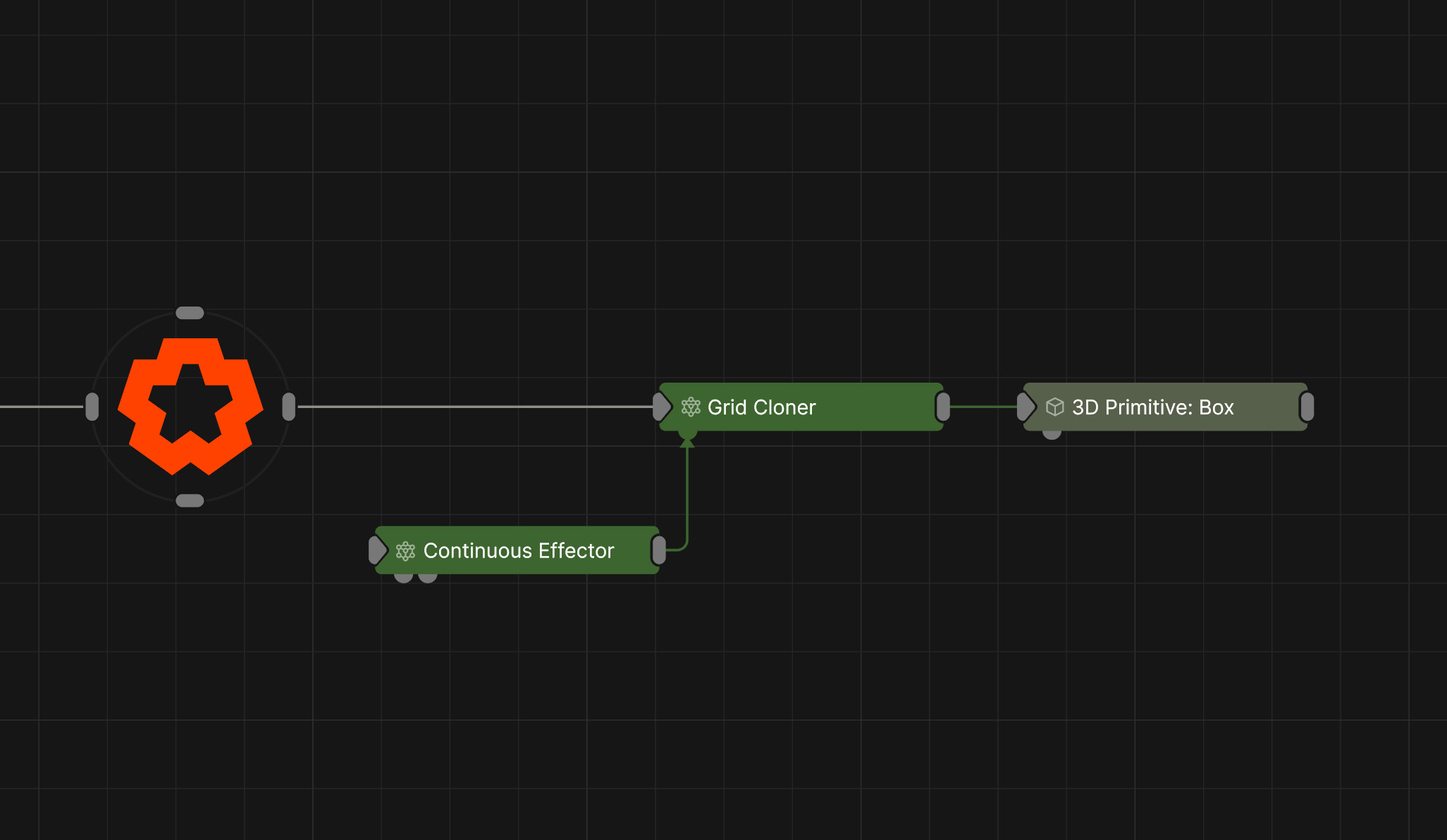
Updated: 12 Jun 2026
This node applies a continuous rotation, scale and translation to every clone.
This node applies a rotation, scale and translation to every clone. The values applied are based on time, allowing for creation of continuous / linear patterns of movement. The Effector Transform parameters determine the rotation, scale and translation that will be applied to the clones, and the method of continuous motion. The amount the translation, scale and rotation are applied to each clone is weighted depending on the falloff function. The effector’s falloff is generated using the effector node’s transform and the Falloff parameters. The falloff shape is determined by the Falloff Mode parameter, with a radius provided by the Falloff parameter and a box falloff from the Falloff Size parameter. The way in which the effector’s rotation, scale and translation are applied to the clone is determined by the Position/Rotation/Scale Apply Mode parameters.
| Parameter | Details |
|---|---|
| Position X | The objects position along the local x-axis. |
| Position Y | The objects position along the local y-axis. |
| Position Z | The objects position along the local z-axis. |
| Rotation Heading | The objects rotation around the local y-axis. |
| Rotation Pitch | The objects rotation around the local x-axis. |
| Rotation Bank | The objects rotation around the local z-axis. |
| Scale X | The objects scale along the local x-axis. |
| Scale Y | The objects scale along the local y-axis. |
| Scale Z | The objects scale along the local z-axis. |
Control the inheritance of the transforms from the parent.
These properties control the core behaviours of the node.
| Parameter | Details |
|---|---|
| Blend Amount | Controls the amount the resulting transforms of each clone after the effector is applied is blended with the original transform. |
| Space |
The transform space in which the effector is processed.
|
| Animation Rate | How quickly the effector animates across the clones. |
| Update Time Mode |
Change how the clone animation uses time.
|
These properties control where an effector can affect the clones.
| Parameter | Details |
|---|---|
| Falloff Mode |
Which shape to use to calculate the falloff.
|
| Falloff Axis | Which axis the falloff should be oriented on. |
| Falloff Direction |
When using Planar mode, which directions to use to calculate the falloff.
|
| Falloff Easing Mode |
Interpolation method used to calculate the falloff within its range of influence.
|
| Falloff Size X | Size of the falloff range along the X axis. |
| Falloff Size Y | Size of the falloff range along the Y axis. |
| Falloff Size Z | Size of the falloff range along the Z axis. |
| Outer Range | Outer range of the falloff, outside of which the falloff is no longer effective. |
| Inner Range | Inner range of the falloff, inside of which the falloff is fully effective. |
| Invert | Inverts the effect of the falloff. |
| Curve Power | Controls the rate of change for the falloff between the inner and outer range. |
These properties control the selection of clones that you want the effector to influence.
| Parameter | Details |
|---|---|
| Selection Mode |
Set the mode for Index-Based Weighting.
|
| Selection Operation |
Set how you want top define the selection.
|
| Index | The first clone index in the range. |
| Max Index | The last clone index in the range. |
| Index Step | The increment used in “Step” mode. |
| Index Seed | The seed used in “Random In Range” mode. |
| Index Falloff Range | Falloff amount for Index-Based Weighting. |
| Index Falloff Power | The curve power of the falloff for Index-Based Weighting. |
| Parameter | Details |
|---|---|
| Position X | The rate of motion - amount per second - applied to the position x channel. |
| Position X Time Offset | The offset applied to the time for the position x channel. |
| Position X Random Offset | The random offset applied to the rate of motion of the position x channel. |
| Position X Step Offset | The linear variation by clone index applied to the rate of motion of the position x channel. |
| Position X Loop Mode |
The loop mode of the continuous motion in the position x channel.
|
| Position X Min | The minimum value of position x. |
| Position X Max | The maximum value of position x. |
| Position Y | The rate of motion - amount per second - applied to the position y channel. |
| Position Y Time Offset | The offset applied to the time for the position y channel. |
| Position Y Random Offset | The random offset applied to the rate of motion of the position y channel. |
| Position Y Step Offset | The linear variation by clone index applied to the rate of motion of the position y channel. |
| Position Y Loop Mode |
The loop mode of the continuous motion in the position y channel.
|
| Position Y Min | The minimum value of position y. |
| Position Y Max | The maximum value of position y. |
| Position Z | The rate of motion - amount per second - applied to the position Z channel. |
| Position Z Time Offset | The offset applied to the time for the position Z channel. |
| Position Z Random Offset | The random offset applied to the rate of motion of the position Z channel. |
| Position Z Step Offset | The linear variation by clone index applied to the rate of motion of the position Z channel. |
| Position Z Loop Mode |
The loop mode of the continuous motion in the position Z channel.
|
| Position Z Min | The minimum value of position Z. |
| Position Z Max | The maximum value of position Z. |
| Rotation Heading | The rate of motion - amount per second - applied to the Rotation Heading channel. |
| Rotation Heading Time Offset | The offset applied to the time for the Rotation Heading channel. |
| Rotation Heading Random Offset | The random offset applied to the rate of motion of the Rotation Heading channel. |
| Rotation Heading Step Offset | The linear variation by clone index applied to the rate of motion of the Rotation Heading channel. |
| Rotation Heading Loop Mode |
The loop mode of the continuous motion in the Rotation Heading channel.
|
| Rotation Heading Min | The minimum value of Rotation Heading. |
| Rotation Heading Max | The maximum value of Rotation Heading. |
| Rotation Pitch | The rate of motion - amount per second - applied to the Rotation Pitch channel. |
| Rotation Pitch Time Offset | The offset applied to the time for the Rotation Pitch channel. |
| Rotation Pitch Random Offset | The random offset applied to the rate of motion of the Rotation Pitch channel. |
| Rotation Pitch Step Offset | The linear variation by clone index applied to the rate of motion of the Rotation Pitch channel. |
| Rotation Pitch Loop Mode |
The loop mode of the continuous motion in the Rotation Pitch channel.
|
| Rotation Pitch Min | The minimum value of Rotation Pitch. |
| Rotation Pitch Max | The maximum value of Rotation Pitch. |
| Rotation Bank | The rate of motion - amount per second - applied to the Rotation Bank channel. |
| Rotation Bank Time Offset | The offset applied to the time for the Rotation Bank channel. |
| Rotation Bank Random Offset | The random offset applied to the rate of motion of the Rotation Bank channel. |
| Rotation Bank Step Offset | The linear variation by clone index applied to the rate of motion of the Rotation Bank channel. |
| Rotation Bank Loop Mode |
The loop mode of the continuous motion in the Rotation Bank channel.
|
| Rotation Bank Min | The minimum value of Rotation Bank. |
| Rotation Bank Max | The maximum value of Rotation Bank. |
| Scale X | The rate of motion - amount per second - applied to the Scale X channel. |
| Scale X Time Offset | The offset applied to the time for the Scale X channel. |
| Scale X Random Offset | The random offset applied to the rate of motion of the Scale X channel. |
| Scale X Step Offset | The linear variation by clone index applied to the rate of motion of the Scale X channel. |
| Scale X Loop Mode |
The loop mode of the continuous motion in the Scale X channel.
|
| Scale X Min | The minimum value of Scale X. |
| Scale X Max | The maximum value of Scale X. |
| Scale Y | The rate of motion - amount per second - applied to the Scale Y channel. |
| Scale Y Time Offset | The offset applied to the time for the Scale Y channel. |
| Scale Y Random Offset | The random offset applied to the rate of motion of the Scale Y channel. |
| Scale Y Step Offset | The linear variation by clone index applied to the rate of motion of the Scale Y channel. |
| Scale Y Loop Mode |
The loop mode of the continuous motion in the Scale Y channel.
|
| Scale Y Min | The minimum value of Scale Y. |
| Scale Y Max | The maximum value of Scale Y. |
| Scale Z | The rate of motion - amount per second - applied to the Scale Z channel. |
| Scale Z Time Offset | The offset applied to the time for the Scale Z channel. |
| Scale Z Random Offset | The random offset applied to the rate of motion of the Scale Z channel. |
| Scale Z Step Offset | The linear variation by clone index applied to the rate of motion of the Scale Z channel. |
| Scale Z Loop Mode |
The loop mode of the continuous motion in the Scale Z channel.
|
| Scale Z Min | The minimum value of Scale Z. |
| Scale Z Max | The maximum value of Scale Z. |
| Parameter | Details |
|---|---|
| Apply To Position | Toggles whether positions are affected. |
| Apply To Rotation | Toggles whether rotations are affected. |
| Apply To Scale | Toggles whether scales are affected. |
| Position Apply Mode |
The method by which the effector position offset is applied to the clone.
|
| Rotation Apply Mode |
The method by which the effector rotation offset is applied to the clone.
|
| Scale Apply Mode |
The method by which the effector scale offset is applied to the clone.
|
The properties control the time at which the node is active. See Timeline for editing time segments.
| Parameter | Details |
|---|---|
| Duration |
Control the duration of the node’s time segment.
|
| Node Time | The custom start and end time for the node. |
| Duration (Timecode) | The length of the node’s time segment (in time). |
| Duration (Frames) | The length of the node’s time segment (in frames). |
| Time Segment Enabled | Set whether the node’s time segment is enabled or not in the Timeline. |
| Name | Description | Typical Input |
|---|---|---|
| Procedural Falloff | Use a procedural system to generate falloff from. Useful for creating complex and unconventional falloffs from an Effector. | Procedural Root |
| Transform Modifiers | Apply the transforms of another node to this node. | Null |
| Target Node | Modifiy the rotations of the node to always direct the z axis towards the input. | Null |
| Local Transform Override | Apply the transforms of another node to this node, relative to its parent. | Null |