Float Array To Points
Updated: 19 Jun 2026
Creates a set of points from a float array.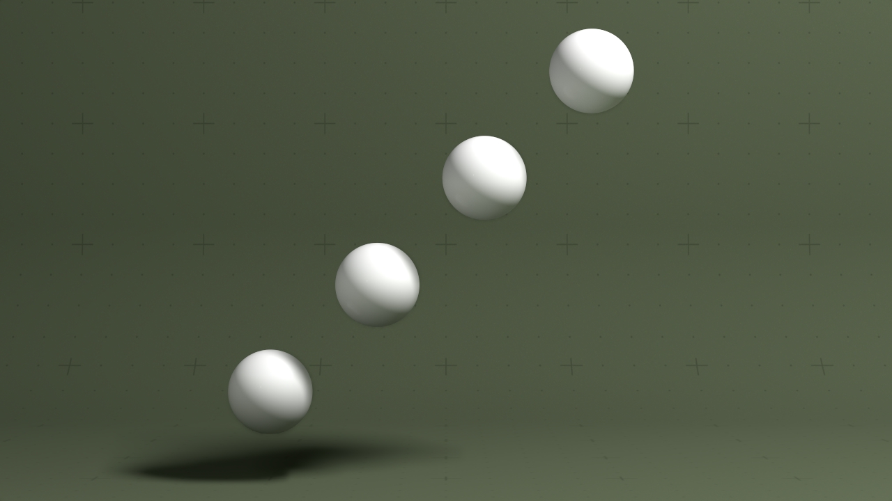
Updated: 19 Jun 2026
Creates a set of points from a float array.
This node takes a Float Array as an input, and uses it to create a set of 3d points. Each point is visualised directly by the node, with basic spheres of any radius and a material input.
This can then be used like any other 3D node within your project, and can be connected to a Mesh Cloner or a Transform Array to instantiate clones or distinct copies of other nodes based on the points of the array.
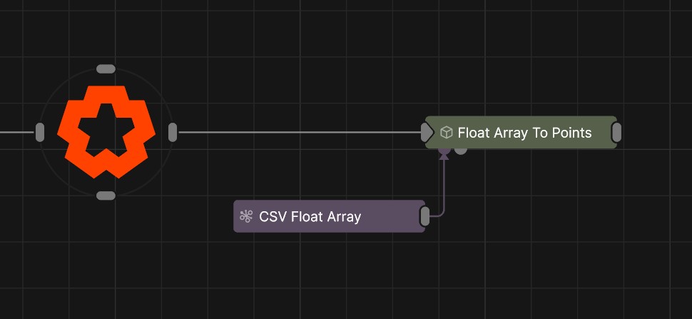
The float array can be created from a Float Array node, a CSV Float Array node or an OSC Float Array node. This can be a useful way of getting multiple sets of position data from external sources into Notch to be able to use them.
The float array provided to the node will be interpreted in either 1D, 2D or 3D. The padding property can be used to determine how extra bits of data sit between the values you want to use to create your points.
| Parameter | Details |
|---|---|
| Position X | The objects position along the local x-axis. |
| Position Y | The objects position along the local y-axis. |
| Position Z | The objects position along the local z-axis. |
| Rotation Heading | The objects rotation around the local y-axis. |
| Rotation Pitch | The objects rotation around the local x-axis. |
| Rotation Bank | The objects rotation around the local z-axis. |
| Scale X | The objects scale along the local x-axis. |
| Scale Y | The objects scale along the local y-axis. |
| Scale Z | The objects scale along the local z-axis. |
| Parameter | Details |
|---|---|
| Position | Toggle inheritance of the Position from the parent. |
| Rotation | Toggle inheritance of the Rotation from the parent. |
| Scale | Toggle inheritance of the Scale from the parent. |
| World Position Only | Inherit the world position from the parent only, rotation and scale will be ignored. Overrides above properties. |
| Inherit Time | Toggle inheritance of time from the parent. |
| Parameter | Details |
|---|---|
| Isolate In Viewport | When enabled, all other objects in the scene will be hidden and only this node will be rendered. |
| Dimension |
Determines how many axis of data you are creating points from.
|
| Padding | The amount of float values from the array that separate what you want to create points from. |
| Offset | Determines what index of the float array will be read as the first value. |
| Radius | Determines the radius of the spheres that are created at each point. |
| Parameter | Details |
|---|---|
| Visible | Control whether the node is visible or not to the scene. |
| Visible To Camera | Is the object visible to the camera. |
| Render As Depth Mask | Renders to depth only, no colour. |
| Visible In Bounces | Is the object calculated in bounce related render properties such as reflections. |
| Casts Shadows | Toggle whether the object can cast shadows. |
| Per Object Composite Alpha | Overwrites the alpha channel beneath the object, giving simple effect of transparency. Best used when the mesh won’t overlap with other objects, as other meshes will not be seen through the mesh. |
| Parameter | Details |
|---|---|
| Lines Visible | Control whether lines are rendered to the scene from the geometry. |
| Lines Alpha | Change the alpha transparency value of the lines, making them appear see-through. |
| Colour | Change the colour value of the lines. |
| Use Vertex Colours | Colour lines based on the vertex colours of the geometry. |
| Blend Mode |
How the object lines blends with the rest of the content in a 3d scene. See Blend Modes for details.
|
| Thick Lines | Allow the lines to rendered with thickness, for line effects which can be accurately anti-aliased. |
| Hide Back Face Lines | Hide the lines generated from polygon faces facing away from the camera, where only the back faces of geometry can be seen. |
| Lock Width | Lock the line width to be a consistent width regardless of distance from the camera. Only functions with Thick Lines enabled. |
| Thick Line Width | Control the thickness of all the lines. Only functions with Thick Lines enabled. |
| Show Silhouette Lines | Draws lines along the edges of the object relative to the camera. |
| Show Normal Difference Lines | Draw a line along the edges of the mesh, depending on the angle difference between their mutual faces. |
| Show Unshared Lines | Draw lines along all edges of the shape. |
| Show Other Lines | Show all the lines for each edge of the mesh. |
| Unshared Lines Weight | Control the strength of the unshared lines. |
| Silhouette Lines Weight | Control the strength of the silhouette lines. |
| Normal Difference Lines Weight | Control the strength of the lines generated along the normal angles. |
| Other Lines Weight | Control the strength of the lines for each edge in the mesh. |
| Line Normal Difference Angle | Change the threshold angle between two face normals that will generate a line along their common edge. Only functions with Show Normal Lines enabled. |
| Line Normal Fade Sharpness | How much the drawn normal lines will fade away the closer the edge angle is to the Line Normal Difference Angle. |
| Line Depth Bias | Exaggerate the width of the lines based on the distance to the camera. not functional with Lock Width enabled. |
| Line Silhouette Fade Sharpness | How much the drawn silhouette lines will fade away based on the size of the edge angle to the camera. |
Preview the objects material in the viewport.
These properties control how the surface of the generated mesh reacts to light in the scene. See Materials for a breakdown of all these properties individually.
The properties control the time at which the node is active. See Timeline for editing time segments.
| Parameter | Details |
|---|---|
| Duration |
Control the duration of the node’s time segment.
|
| Node Time | The custom start and end time for the node. |
| Duration (Timecode) | The length of the node’s time segment (in time). |
| Duration (Frames) | The length of the node’s time segment (in frames). |
| Time Segment Enabled | Set whether the node’s time segment is enabled or not in the Timeline. |
| Name | Description | Typical Input |
|---|---|---|
| Float Array | The float array that will be used to create the points. | Float Array |
| Material | Override the default material with a material node. | Materials |
| Transform Modifiers | Apply the transforms of another node to this node. | Null |
| Parameter Value Array | Used to set the parameters of the node using an array. | Parameter Array |