Transform Affector
Updated: 12 Jun 2026
Affects the position and rotation of physics objects based on the transforms of a given target.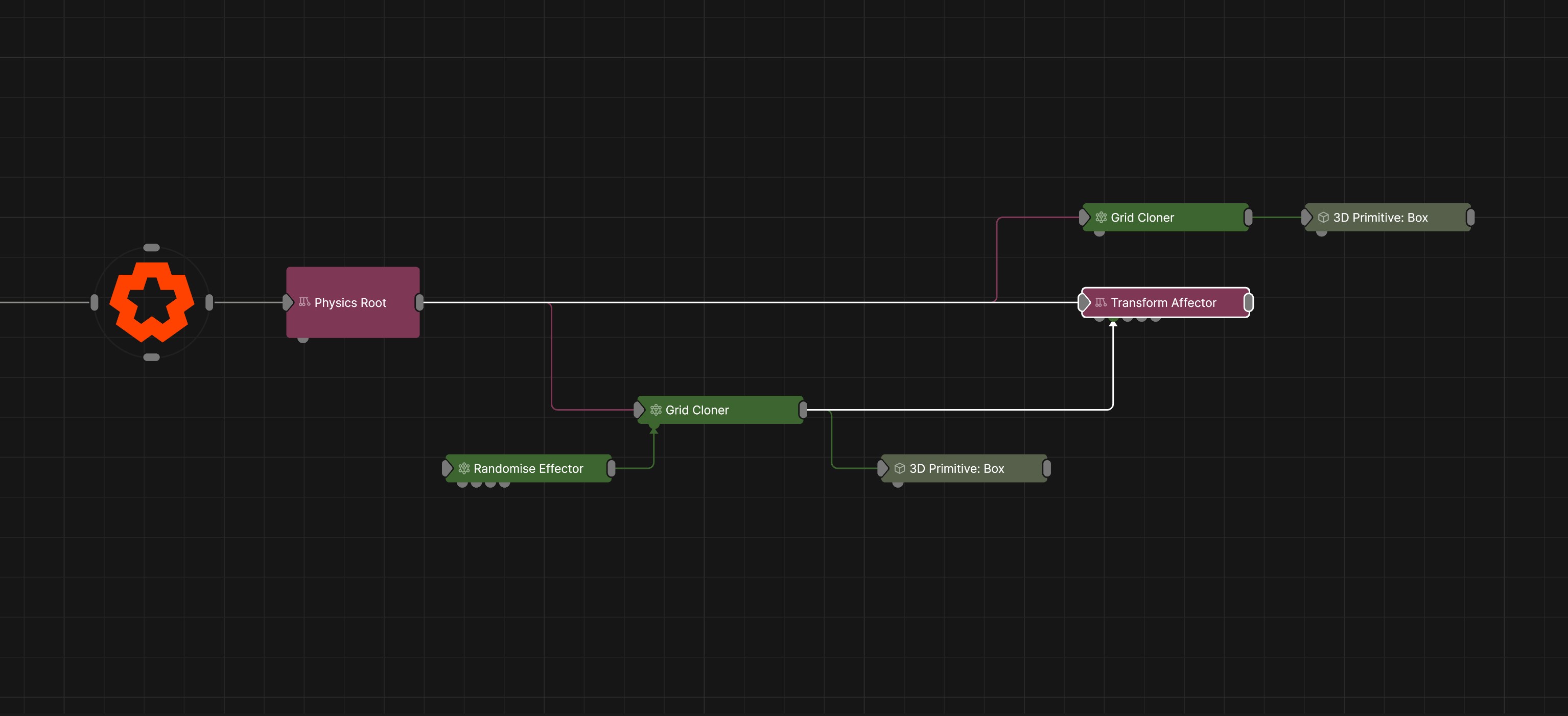
Updated: 12 Jun 2026
Affects the position and rotation of physics objects based on the transforms of a given target.
The node uses the transforms of a target node to influence rigid bodies within a physics system. The target can be a single object or a set of cloned objects. Rigid bodies that fall within the influence of the target node(s) will attempt to match the position and rotation of their corresponding targets.
The Amount and Angular Stiffness parameters control how strongly the rigid bodies are driven towards the target transforms. Higher values cause rigid bodies to follow the target position and rotation more closely, while lower values allow the influence to be applied more gradually, preserving more of the natural physical motion and simulation behaviour.
These properties control the 3D transforms of the node. Transforms will generally be inherited by child nodes, although they can be ignored through the Inherit Transform Channels attributes.
| Parameter | Details |
|---|---|
| Position X | The objects position along the local x-axis. |
| Position Y | The objects position along the local y-axis. |
| Position Z | The objects position along the local z-axis. |
| Rotation Heading | The objects rotation around the local y-axis. |
| Rotation Pitch | The objects rotation around the local x-axis. |
| Rotation Bank | The objects rotation around the local z-axis. |
| Scale X | The objects scale along the local x-axis. |
| Scale Y | The objects scale along the local y-axis. |
| Scale Z | The objects scale along the local z-axis. |
Control the inheritance of the transforms from the parent.
| Parameter | Details |
|---|---|
| Position | Toggle inheritance of the Position from the parent. |
| Rotation | Toggle inheritance of the Rotation from the parent. |
| Scale | Toggle inheritance of the Scale from the parent. |
| World Position Only | Inherit the world position from the parent only, rotation and scale will be ignored. Overrides above properties. |
| Inherit Time | Toggle inheritance of time from the parent. |
These properties control the core behaviours of the node.
| Parameter | Details |
|---|---|
| Amount | Controls how strongly rigid bodies attempt to match the target position. |
| Angular Stiffness | Controls how strongly rigid bodies attempt to match the target rotation. |
| Mode |
The mode of the affector
|
| Target Pivot X | Sets where the center of influence is of the target on the X axis. |
| Target Pivot Y | Sets where the center of influence is of the target on the Y axis. |
| Target Pivot Z | Sets where the center of influence is of the target on the Z axis. |
| Target Falloff |
Apply a falloff to the influence of each target.
|
| Target Falloff Inner | Affectors influence will be at 100% inside this radius. |
| Target Falloff Outer | Affectors will have no influence outside of this radius. |
| Target Falloff Power | Adjusts how rapidly influence increases from the outer falloff to the inner falloff. |
| Dampening | Applies resistance to motion, reducing velocity and creating smoother movement. |
| Randomness | Adds randomness to the amount of positional and rotational influence the affector has. |
These properties are used to set the falloff of the node.
| Parameter | Details |
|---|---|
| Falloff Mode |
Which shape to use to calculate the falloff.
|
| Falloff Axis | Which axis the falloff should be oriented on. |
| Falloff Direction |
When using Planar mode, which directions to use to calculate the falloff.
|
| Falloff Easing Mode |
Interpolation method used to calculate the falloff within its range of influence.
|
| Falloff Size X | Size of the falloff range along the X axis. |
| Falloff Size Y | Size of the falloff range along the Y axis. |
| Falloff Size Z | Size of the falloff range along the Z axis. |
| Outer Range | Outer range of the falloff, outside of which the falloff is no longer effective. |
| Inner Range | Inner range of the falloff, inside of which the falloff is fully effective. |
| Invert | Inverts the effect of the falloff. |
| Curve Power | Controls the rate of change for the falloff between the inner and outer range. |
The properties control the time at which the node is active. See Timeline for editing time segments.
| Parameter | Details |
|---|---|
| Duration |
Control the duration of the node’s time segment.
|
| Node Time | The custom start and end time for the node. |
| Duration (Timecode) | The length of the node’s time segment (in time). |
| Duration (Frames) | The length of the node’s time segment (in frames). |
| Time Segment Enabled | Set whether the node’s time segment is enabled or not in the Timeline. |
| Name | Description | Typical Input |
|---|---|---|
| Falloff Node | Use an input node to control the transformation values of the falloff. | Falloff |
| Transform Target | Define target(s) to apply transform to/from. Input a single target, or use a cloner to target multiple objects. | Null |
| Affected Nodes | Choose which nodes will be affected by the affector. | 3D Primitive |
| Excluded Nodes | Choose which nodes wont be affected by the affector. | 3D Primitive |
| Local Transform Override | Apply the transforms of another node to this node, relative to its parent. | Null |
| Procedural Falloff | Input to use a procedural system to control the falloff | Procedural Root |
| Transform Modifiers | Apply the transforms of another node to this node. | Null |
| Target Node | Modifiy the rotations of the node to always direct the z axis towards the input. | Null |