

Working With Custom Shaders
Updated: 15 Jul 2026
Updated: 15 Jul 2026
This section explains how to use custom shaders to create your own effects. New for version 2026.2 is the ability to create you own Particle Affectors, Cloner Effectors and Deformers.
Custom Shader Effectors require the implementation of your own code to determine the behaviour of the Effector, and requires some knowledge of these systems to implement. Use of custom shaders is at your own risk. 10Bit does not provide support for custom shader code. If you experience an issue with a project/block you will need to demonstrate your issue without your custom shader in the nodegraph, to be able to receive support from the 10bit team. Support is only available for issues specifically related to the functionality of the Custom Shader Node, not for any custom code. External tools are available that can provide good assistance in writing these nodes when provided with the example script and a link to the relevant manual pages.
These nodes let you create your own custom effects using shader code. This is great way of expanding the capabilities of various systems in Notch, and with careful design and implementation can lead to endless possibilities of innovative and efficient looks. Notch shaders are written in HLSL and use the D3DX Effect framework.
Custom Cloner Effectors allow for the manipulation of position, rotation, scale and colours of clones, as well as the killing of clones. For an overview of cloner systems and how to use clone effectors within them, see Cloners.
Custom Particle Affectors allow for the manipulation of velocity, colour, normals, scale (via the normal buffer’s w component) of particles via your own code. For an overview of particle systems and how to use affectors within them, see Particles.
Custom Shader Deformers allow for the manipulation of each individual vertex’s position, motion, normal direction, colour and motion. For an overview of deformers, see Deformers.
Custom Shader Post-FX allow for the manipulation of each individual pixel in a texture. For more info on Post-FX, see Post-FX.
These nodes are all processed once per frame. By writing HLSL code, you can perform operations on that data and use it to update (effect) attributes of clones. You can also define your own variables that can be controlled from the Property Editor or via Modifiers, just like other parameters in Notch.
The simplest method to get working quickly is to have the node generate its example script for you. To do this:
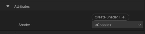
Once you have created a script that you want to re-use in new projects, you can import the .fx file by clicking and dragging it from your file system into the resource browser in Notch. Alternatively, you can click on the import resource button in the Resource Browser. Your shader files can then be assigned to the node inside of the Property Editor.
As soon as you have assigned a shader file to the node, you will see it’s effect as soon as your press play.
To edit the shader file, you need to open it in an external editor. One way to quickly do this:
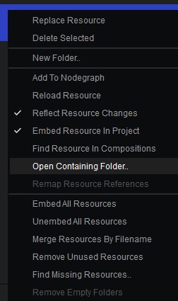
As you will be writing shader code in this file, it is very helpful to work in a text editor that can interpret shader code syntactically.
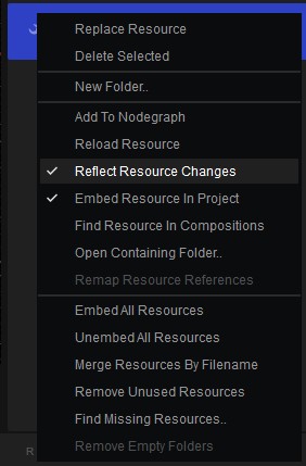
As you will be editing your script outside of Notch, you will need to ensure that the resource is reloaded after you make changes to the .fx file. You can do this manually at any time by right clicking on the resource in the Resource Browser and hitting “Reload Resource”. You can also set this to happen automatically whenever the resource is updated by choosing “Reflect Resource Changes” from the same right mouse button menu. With this option, the shader file will be updated in Notch whenever it is saved over in Windows.
Once you have gotten set up with the example script you are ready to start reading and customising it. Depending on the node that you are creating a shader for, the specific workings of the code will change. However, essentially in each example:
To see the specific functions of each of these nodes, refer to the pages for each specific node, but we will look at how to work with variables and inputs for the custom shader nodes in this article.
All of the above custom shader nodes support the following types of variables. Some types of variable can be controlled via various UI elements:
A float value can be defined like so:
float MyFloat <
string propertyName = "My Float";
float propertyMin = -10.0f;
float propertyMax = 10.0f;
> = 0.0f;
The following annotations can be used for configuring the value’s UI element inside of the node’s properties:
A simple integer value with a slider can be defined like so:
int MyInteger <
string propertyName = "My Integer";
int propertyMin = -10;
int propertyMax = 10;
> = 0;
The following annotations can be used for configuring the value’s UI element inside of the node’s properties:
An integer that can be set to 0 and 1 with the use of a checkbox can be declare like this. The value will be 0 when unchecked, and 1 when checked:
int MyCheckboxVariable <string propertyType = "checkbox"; > = 0;
You can also create a list of options with your own choice of names. This will output an integer that corresponds to the index of the selected item in the list. For example:
int MyMenu <
string propertyName = "Size";
string propertyEnums[] = { "Small", "Big", "Bigger" };
> = 0;
This will create a menu with options displayed as small, big, and bigger and would return 0, 1 or 2 respectively.
It is possible to input textures, transforms, and transform arrays into each of the custom shader nodes. Once the shader file has been loaded in the custom shader node, an input pin will appear that can be fed with the output of another node.
A Texture input can be created with a line of code like this:
Texture2D<float4> MyTextureInput < string propertyName = "Colour Input"; >;
You can read a float4 giving the RGBA values of a texture at a given UV position like this:
float4 pixelValues = MyTextureInput.SampleLevel(LinearWrapSampler, float2(posU,posV), 0);
The two values posU and posV must be floats between 0 and 1, and will be used to set the UV position that you want to read colour from.
You can read individual channels of a texture at a given UV position like this:
float red = MyTextureInput.SampleLevel(LinearWrapSampler, float2(posU,posV), 0).r;
float green = MyTextureInput.SampleLevel(LinearWrapSampler, float2(posU,posV), 0).g;
float blue = MyTextureInput.SampleLevel(LinearWrapSampler, float2(posU,posV), 0).b;
float alpha = MyTextureInput.SampleLevel(LinearWrapSampler, float2(posU,posV), 0).a;
Transforms use 4x4 float matrices. You can create a transform input pin to your node like this:
float4x4 Trans_Target;
Before you can easily work with your transform values in your HLSL file, you will need to convert the matrix into readable values. These formulas are useful for working with transform inputs in HLSL:
// A function to get the position of an input transform matrix.
float3 GetPosition(float4x4 m)
{
    return float3(m[3][0], m[3][1], m[3][2]);
}
// A function to get the scale values of an input transform matrix.
float3 GetScale(float4x4 m)
{
    float3 scale;
    scale.x = length(float3(m[0][0], m[1][0], m[2][0]));
    scale.y = length(float3(m[0][1], m[1][1], m[2][1]));
    scale.z = length(float3(m[0][2], m[1][2], m[2][2]));
    return scale;
}
// A function to get the rotation of a 4x4 transform matrix in the form of a 3x3 rotation matrix.
float3x3 GetRotation(float4x4 m)
{
    float3 scale = GetScale(m);
    float3x3 rotation;

    rotation[0][0] = m[0][0] / scale.x;
    rotation[1][0] = m[1][0] / scale.x;
    rotation[2][0] = m[2][0] / scale.x;

    rotation[0][1] = m[0][1] / scale.y;
    rotation[1][1] = m[1][1] / scale.y;
    rotation[2][1] = m[2][1] / scale.y;

    rotation[0][2] = m[0][2] / scale.z;
    rotation[1][2] = m[1][2] / scale.z;
    rotation[2][2] = m[2][2] / scale.z;

    return rotation;
}
The custom shader node’s buffers are built around using rotation as Euler angles. You will need to convert your 3x3 rotation matrix to Euler angles like so:
float3 MatrixToEuler(float3x3 m)
{
    float3 euler;
    euler.x = atan2(m[2][1], m[2][2]);                                   // pitch
    euler.y = atan2(-m[2][0], sqrt(m[2][1]*m[2][1] + m[2][2]*m[2][2]));  // yaw
    euler.z = atan2(m[1][0], m[0][0]);                                   // roll
    return euler;
}
You can create an array of transforms like this:
float4x4 Trans_Array[16];
This will create a new pin on your node, that you can either connect multiple nodes with transforms to, or a transform array node. You can create multiple objects to this input pin to access their transforms. The array will be pe populated with the inputting nodes sorted by their nodegraph position, from top to bottom and left to right. See Node Hierarchy and Data Flow.
To get how many of those slots are actually connected and populated, you declare a plain int with the array’s name plus _Count:
int Trans_Array_Count;
You can access an individual transforms from a transform array, and it’s corresponding position, scale and rotation by using the following in combination with the formulas shown above:
if (Trans_Array_Count > 0)
{
    for (uint i = 0; i < (uint)Trans_Array_Count; i++)
    {
        float3 pos    = GetPosition(Trans_Array[i]);
        float3 scale  = GetScale(Trans_Array[i]);
        float3x3 rot  = GetRotation(Trans_Array[i]);
        // do something per-transform here
    }
}