Procedural Affector
Updated: 15 Dec 2025
Allows particles to interact with procedurals.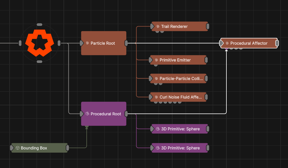
Updated: 15 Dec 2025
Allows particles to interact with procedurals.
This node simulates collisions between particles and Procedural meshing object. Different effects can be achieved, such as attraction and repulsion from object surfaces or making particles flow around the particle surface, as selected by the Mode parameter.
At least one Procedural Object Node must be connected via the Procedural Nodes input for this node to be effective.
These properties control the core behaviours of the node.
| Parameter | Details |
|---|---|
| Mode |
Choose how the node interacts with the input object.
|
| Velocity Scale | Scale the strength of the affectors velocity on the particles. |
| Radius | Limit the radius at which particles can be affected by the affector. |
| Life Effect Coeffs | How much the particles are affected by the affector at different stages of the particles life cycle. Values 1 and 2 are control points used to control a bezier curve between values 0 and 3. |
| Colour Weight | Controls how much the colour value generated by the affector is blended with the particle’s current colour. |
| Collision Velocity Scale | Scales the velocity of the particle after a collision so they can be made to slow down. |
| Is Inside Threshold | Distance inside or outside the object at which collisions are considered to have occured. |
| Surface Distance Target | The radius of the particle when determining collisions. |
| On Surface Velocity Scale | Scales the velocity of the particle when it is on the surface of the object. |
| Collision Event Likeliness | Controls for what fraction of collisions a collision event should be triggered. |
| Use Colours | Toggle whether to use the colours input by the mesh. |
| Invert Space | Invert the object so areas inside the mesh are considered hollow and areas outside are filled. |
These properties are used to set the falloff of the node.
| Parameter | Details |
|---|---|
| Falloff Mode |
Which shape to use to calculate the falloff.
|
| Falloff Axis | Which axis the falloff should be oriented on. |
| Falloff Direction |
When using Planar mode, which directions to use to calculate the falloff.
|
| Falloff Easing Mode |
Interpolation method used to calculate the falloff within its range of influence.
|
| Falloff Size X | Size of the falloff range along the X axis. |
| Falloff Size Y | Size of the falloff range along the Y axis. |
| Falloff Size Z | Size of the falloff range along the Z axis. |
| Outer Range | Outer range of the falloff, outside of which the falloff is no longer effective. |
| Inner Range | Inner range of the falloff, inside of which the falloff is fully effective. |
| Invert | Inverts the effect of the falloff. |
| Curve Power | Controls the rate of change for the falloff between the inner and outer range. |
The properties control the time at which the node is active. See Timeline for editing time segments.
| Parameter | Details |
|---|---|
| Duration |
Control the duration of the node’s time segment.
|
| Node Time | The custom start and end time for the node. |
| Duration (Timecode) | The length of the node’s time segment (in time). |
| Duration (Frames) | The length of the node’s time segment (in frames). |
| Time Segment Enabled | Set whether the node’s time segment is enabled or not in the Timeline. |
| Name | Description | Typical Input |
|---|---|---|
| Falloff Node | Use an input falloff node to override the falloff. | Falloff |
| Procedural Node | The source Procedural mesh for the particles to be affected by. | Procedural Meshing |
| Affected Emitters | Choose which particle emitters can be affected by the affector. | Primitive Emitter |
| Procedural Falloff | Use the distance field from a procedural system to vary how strong the affector is. | Procedural Root |
| Weights | Add a particle weight node to vary the node’s effect on the particle system. | Noise Weight |
| Transform Modifiers | Apply the transforms of another node to this node. | Null |
| Target Node | Modifiy the rotations of the node to always direct the z axis towards the input. | Null |
| Local Transform Override | Apply the transforms of another node to this node, relative to its parent. | Null |