Hokuyo UST Lidar Array
Generates an Array from a Hokuyo 2D LiDAR.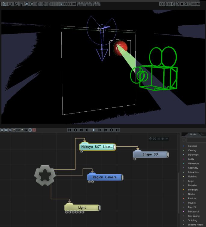
This node creates an Array of points on the basis of a Hokuyo 2D LiDAR. At a high level, the node allows you to specify a rectangular region of interest and identify objects/hands/people within that zone. These objects become transforms/points in the array that can be used to spawn various other node instances (Particle emitters etc.) See the Array Source section for more details.
Notch connects to the Hokuyo sensor via TCP/IP which is configured in the Devices->Mo-cap/Camera/Streaming Device Settings.
You can address up to 4x Hokuyo sensors from Notch.
Support for the Hokuyo sensor requires a Notch Pro license.
The output transform array may be used directly with a Clone To Transform Array, or to clone other nodes within a Field System or Particle System.
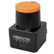
Hokuyo produce a range of 2D LiDAR range finders. The models supported by Notch utilise the SCIP 2 protocol which runs over an IP network (100Base link).
The sensors sweep a 270 degree area grabbing the distance from the sensor at step intervals. The various UST models differ in the range that they can cover and the number of step increments of measurement (0.25 or 0.125 degree steps).
The Hokuyo sensor requires you to source your own power supply and connect it by stripping wires.
The Hokuyo sensor utilises a 100Base network link. Please check your network card can support 100Base (some only now support 1000Base or 10000Base).
The following models are known to work with Notch.
Details on each of the sensors are available on the Hokuyo website
If you are purchasing within Europe we recommend speaking to Sentek Europe.
The user community have found the following accessories useful when working with the Hokuyo sensor:
Manfrotto Super Clamps and Magic Arms are also useful for temporary mounting.
Notch connects directly to the Hokuyo sensor, so no middleware or driver software is required. However, various diagnostic software is available for the Hokuyo units - one of the better ones is: URGBenri
Connect power to the LiDAR sensor and connect an ethernet cable to your PCs network card.
The sensor by default has the following IP setup:
192.168.0.10255.255.255.010940Therefore it is easiest to set your network adapter to use the IP address:
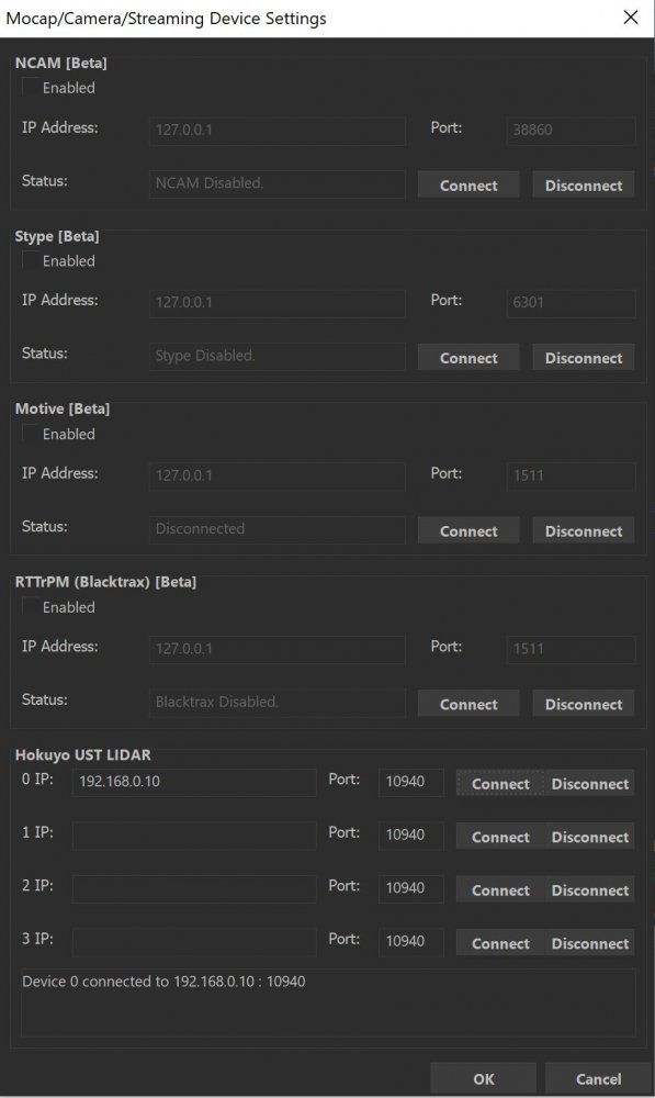
192.168.0.xxx (where xxx is 1-255 and is not 10).255.255.255.0In Notch go to Devices->Mo-cap/Camera/Streaming Device Settings. At the bottom of the window is the Hokuyo settings, put the LiDAR IP address (192.168.0.10) and the port number is 10940. Press connect, You will see at the bottom of the window that the device is now connected.
The sensor will only accept one network connection, meaning only one PC/standalone/block/piece of software can talk to the sensor at a time.
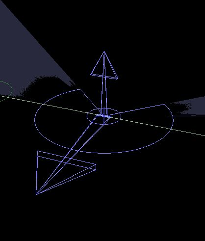
Once you’ve added the Hokuyo UST LiDAR node, you can see a wireframe visual representation of the sensor and its data by turning on the Bounding Box view. The arrows align as follows to the physical server. (Please note the black notch on the top of the sensor represents the ‘back’ of the sweep - i.e. the dead area).
When setting up the sensor, it’s useful to see the bounding box view while playing. To do this turn on View->Show Bounding Boxes and Range Finders while Playing.
The raw sensor data (represented by the blue lines) will only update while playing.
The representation of the arrows is demonstrated below.
| Physical Orientation | Notch Orientation |
|---|---|
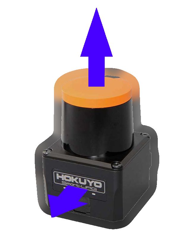
|
|
Use the arrows to match the orientation of the sensor to the real world. You can do this via the Transform Position & Rotation attributes and you can use the Sensor Rotation Offset attribute for fine-grain changes.
When initially setting up the Hokuyo node, it’s best not to change the scale.
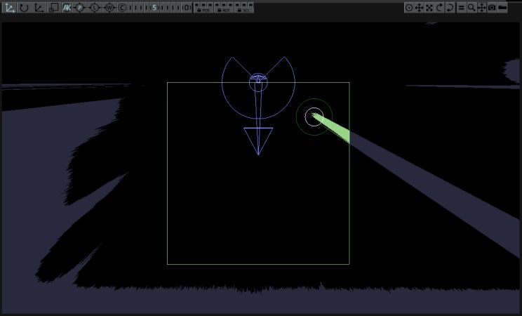
The region of interest is the area you actively want to track with the sensor, while excluding objects outside it. This could be the area of an LED screen, or the area of a floor. It is represented by the nodes green bounding box.
The sensor works in real metres. So when setting up your bounds, you’ll be working in metres. With Bounding Box visibility turned on, you will want to ‘find’ the active area. This is most easily done by placing people/objects/hands at each corner of the area of interest and then altering the Bounds: -X, +X, -Y, +Y attributes to find the edge of the subjects.
Where masses are seen within the region of interest (bounds), they will be analysed and a ‘point’ assigned to it and output within the Array. There are various attributes that can be used to fine-tune this analysis, but the default settings should work for detecting hands/wrists over surfaces >1m across.
The sensor returns a set of several thousand sample points per frame, arranged as a continuous circular sweep from the sensor outwards. This data is processed to determine a much smaller set of points of interest, which should correspond to e.g. the hands of a user interacting with the space. This process takes several stages. First, the points are culled by the bounding region. Then the remaining points are joined together into contours, which should represent single objects - e.g. a single contour for one person visible to the sensor. Next, the most relevant points are extracted from the sensor. This looks for points on the contour which are closest to the sensor but also separated from each other by both distance, and angle along the sensor sweep. The resulting points are then merged. In order to achieve some temporal coherence in the point data set, the set of points detected in the current frame are matched to the points in the previous frame. If found, current positions may be smoothed against the previous position to reduce temporal jitter.
As mentioned previously there are various parameters that can be used to fine tune this process. Typically this is a compromise between detail and smoothness: detection of small features (like fingers) may come at the compromise of an increase in jitter; smoothness may come at the cost of reduced fine-grained accuracy. The tuning will depend on both the scale of interaction and the desired use of the result in effects / content.
When creating content for real-world sensors you have two spaces you need to bring together: the sensor space and the visual space. You have two options when it comes to moving and scaling these spaces.
After you have calibrated the sensor, it is often best to uniformly scale and move the sensor to the visual effect area. Often it’s very useful to use a Region Camera to align the two areas together.
In this example, we have Shape 3D nodes being spawned where an object is found in the region of interest. We’ve also used a Region Camera to match the two spaces (both sensor and visual world together).
These properties control the 3D transforms of the node. Transforms will generally be inherited by child nodes, although they can be ignored through the Inherit Transform Channels attributes.
| Parameter | Details |
|---|---|
| Position X | {Move its position along the x-axis in local space. |
| Position Y | Move its position along the y-axis in local space. |
| Position Z | Move its position along the z-axis in local space. |
| Rotation Heading | Rotate the object about the x-axis. |
| Rotation Pitch | Rotate the object about the y-axis. |
| Rotation Bank | Rotate the object about the z-axis. |
| Scale X | Scale along the x-axis. |
| Scale Y | Scale along the y-axis. |
| Scale Z | Scale along the z-axis. |
Toggle which transform channels should be inherited from the parent node. By default, all transforms will be inherited.
| Parameter | Details |
|---|---|
| Position X | Toggle inheritance of the X Position from the parent. |
| Position Y | Toggle inheritance of the Y Position from the parent. |
| Position Z | Toggle inheritance of the Z Position from the parent. |
| Rotation Heading | Toggle inheritance of the Rotation Heading from the parent. |
| Rotation Pitch | Toggle inheritance of the Rotation Pitch from the parent. |
| Rotation Bank | Toggle inheritance of the Rotation Bank from the parent. |
| Scale X | Toggle inheritance of the X Scale from the parent. |
| Scale Y | Toggle inheritance of the Y Scale from the parent. |
| Scale Z | Toggle inheritance of the Z Scale from the parent. |
| World Position Only | Inherit the world position from the parent only, rotation and scale will be ignored. Overrides above properties. |
| Inherit Time | Toggle inheritance of time from the parent. |
These properties control the core behaviours of the node.
| Parameter | Details |
|---|---|
| Apply Node Transforms To Array Elements Only | When enabled, each point is passes its world space translation to child nodes. When disabled, passes a full transform - position/rotation/scale - to child nodes. |
| Sensor Index | Select which connected lidar sensor to use. |
| Sensor Rotation Offset | Sets the rotation offset applied to the sensor data before any further processing - including any bounds clipping. Used to make sensor orientation and setup easier. |
| Cluster Distance Threshold | The maximum distance to the sensor that is allowed, when detecting points along a contour, from the closest point on the contour to the camera and each given point. |
| Min Distance Threshold | Controls the minimum distance allowed between multiple points extracted from a contour. Larger values will give less points. |
| Min Angle Separation | Controls the minimum angle allowed between multiple points extracted from a contour. Larger values will give less points. |
| Merge Points Distance | The distance within which multiple points may be merged together into a single point. The resultant position is the average of merged points. Larger values merge more points together. |
| Previous Points Track Distance Tolerance | Controls the maximum distance from a point in the current frame and the previous frame, when detecting a point’s correspondence to a point in the previous frame. |
| Smoothing Distance | The distance between a point in the current frame and it’s position in the last frame in which motion is smoothed. Larger values will create smoother motions but may increase latency. |
| Flip X Axis | Flip the X axis of the incoming point data. |
| Flip Y Axis | Flip the Y axis of the incoming point data. |
Set the bounding dimensions of the incoming data, and the area within which points will be generated.
These properties control how an element is eased into an array.
| Parameter | Details |
|---|---|
| Ease Points On | Enable Point Easing in, so new points don’t immediately appear. |
| Ease Points On Mode | Edit the easing curve for how the new points will appear.
|
| Ease Points On Duration | How long the points should take to fully appear. |
| Ease Points Off | Enable Point Easing out, so removed points don’t immediately disappear. |
| Ease Points Off Mode | Edit the easing curve for how the removed points will disappear.
|
| Ease Points Off Duration | How long the points should take to fully disappear. |
| Easing Points Affects Point Scales | Allow the points to scale in size while easing. |
| Easing Points Affects Point Opacities | Allow the points to fade the opacity of objects while easing. |
| Name | Description | Typical Input |
|---|---|---|
| Point Array Source | ||
| Bounding Box | To be used for the play area of the sensor. | |
| Transform Modifiers | Apply the transforms of another node to this node. | Null |
| Target Node | Modifiy the rotations of the node to always direct the z axis towards the input. | Null |
| Local Transform Override | Apply the transforms of another node to this node, relative to its parent. | Null |