Soft Ball Renderer
Updated: 13 Jan 2026
Renders particles as soft body spheres.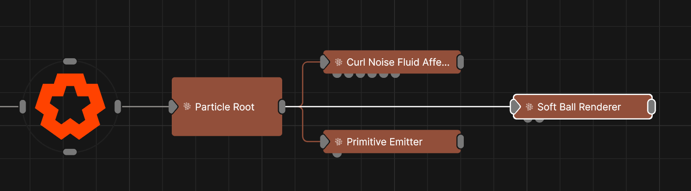
Updated: 13 Jan 2026
Renders particles as soft body spheres.
This node uses an approximated soft body simulation to render particle as soft spheres. The spheres can interact with each other softly, like spherical soft bodies, and also be constrained by collisions using particle collision affectors such as the Primitive Collision Affector.
This node generates geometry for each particle and can accumulate lots of geometry very fast when using a lot of particles. To reduce the amount of geometry generated, either lower the “Num Particles” in the Particle Root node, and / or reduce the amount of "Subdivisions" in the Soft Ball Renderer node.
These properties control the core behaviours of the node.
| Parameter | Details |
|---|---|
| Max Radius | Maximum size of the ball. |
| Radius Randomness | How much randomness in the size of the ball. |
| Spring Dampening | How much to dampen the springiness effect applied to the particles. |
| Smooth Iterations | How much smoothing to apply to the geometry of the balls. |
| Use Particle Colours | If enabled then the colour of each ball will be taken from it’s particle. |
| Subdivisions | How much to subdivide the geometry of the balls. |
| Max Generated Vertices | Readout of how many vertices will be generated if all particles are spawned. |
| Num Particles Used | Readout of the maximum amount of particles in the root. |
| Visible | Control whether the node is visible or not to the scene. |
| Seen By Rays | Allow the mesh to be seen by the raytracer. When set to 0, the mesh will still render in camera but will be ignored by any raytracing nodes. |
These properties add options for drawing all the edges of the mesh as lines. Useful for rendering wireframe effects.
| Parameter | Details |
|---|---|
| Lines Visible | Control whether lines are rendered to the scene from the geometry. |
| Lines Alpha | Change the alpha transparency value of the lines, making them appear see-through. |
| Colour | Change the colour value of the lines. |
| Use Vertex Colours | Colour lines based on the vertex colours of the geometry. |
| Blend Mode |
How the object lines blends with the rest of the content in a 3d scene. See Blend Modes for details.
|
| Thick Lines | Allow the lines to rendered with thickness, for line effects which can be accurately anti-aliased. |
| Hide Back Face Lines | Hide the lines generated from polygon faces facing away from the camera, where only the back faces of geometry can be seen. |
| Lock Width | Lock the line width to be a consistent width regardless of distance from the camera. Only functions with Thick Lines enabled. |
| Thick Line Width | Control the thickness of all the lines. Only functions with Thick Lines enabled. |
| Show Silhouette Lines | Draws lines along the edges of the object relative to the camera. |
| Show Normal Difference Lines | Draw a line along the edges of the mesh, depending on the angle difference between their mutual faces. |
| Show Unshared Lines | Draw lines along all edges of the shape. |
| Show Other Lines | Show all the lines for each edge of the mesh. |
| Unshared Lines Weight | Control the strength of the unshared lines. |
| Silhouette Lines Weight | Control the strength of the silhouette lines. |
| Normal Difference Lines Weight | Control the strength of the lines generated along the normal angles. |
| Other Lines Weight | Control the strength of the lines for each edge in the mesh. |
| Line Normal Difference Angle | Change the threshold angle between two face normals that will generate a line along their common edge. Only functions with Show Normal Lines enabled. |
| Line Normal Fade Sharpness | How much the drawn normal lines will fade away the closer the edge angle is to the Line Normal Difference Angle. |
| Line Depth Bias | Exaggerate the width of the lines based on the distance to the camera. not functional with Lock Width enabled. |
| Line Silhouette Fade Sharpness | How much the drawn silhouette lines will fade away based on the size of the edge angle to the camera. |
Preview the objects material in the viewport.
These properties control how the surface of the generated mesh reacts to light in the scene. See Materials for a breakdown of all these properties individually.
The properties control the time at which the node is active. See Timeline for editing time segments.
| Parameter | Details |
|---|---|
| Duration |
Control the duration of the node’s time segment.
|
| Node Time | The custom start and end time for the node. |
| Duration (Timecode) | The length of the node’s time segment (in time). |
| Duration (Frames) | The length of the node’s time segment (in frames). |
| Time Segment Enabled | Set whether the node’s time segment is enabled or not in the Timeline. |
| Name | Description | Typical Input |
|---|---|---|
| Material | Add a material to override the internal default material. | Material |
| Rendered Emitters | Specify which emitters are rendered using this renderer. By default, all emitters connected to the same particle root as the renderer are rendered. | Primitive Emitter |
| Transform Modifiers | Apply the transforms of another node to this node. | Null |
| Target Node | Modifiy the rotations of the node to always direct the z axis towards the input. | Null |
| Local Transform Override | Apply the transforms of another node to this node, relative to its parent. | Null |