Spline
Updated: 30 Jan 2026
This node defines a spline in 3D space from a number of control points.
Updated: 30 Jan 2026
This node defines a spline in 3D space from a number of control points.
This node defines a spline in 3D space from a number of control points.
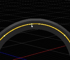
This node can be picked / selected in the viewport if it has a connection to a root object in the node hierarchy,
by hovering over the spline (it highlights) and LMB clicking it.Editing Spline nodes in the viewport is compatible with perspective and orthographic views / cameras but not in Warped perspective cameras.
Spline nodes can also be edited in 2D space as a child node of a 2D Root.
Control points may be added by:
Clicking the ‘Tangent’ button to enter tangent aligned add point mode from the ‘Add Point Direction’ property on the properties pane

Adding points will inherit the direction from the previous point tangent so will appear offset (in the new point case) from the previous point along the tangent vector.
LMB clicking in-between two existing spline points, along the spline to add a new point at the intersection point
Clicking the ‘Paint’ button to enter painting mode from the ‘Add Point Direction’ property on the properties pane
Points can be painted on either end of the spline by selecting the ‘Add To Nearest End Point’ checkbox on the properties pane
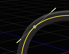
When you have a single spline point selected, spline point properties for that point are shown in the property editor to fine tweak the position, rotation and scale of the spline shape and its attached geometry nodes.
Spline points have a number of interpolation modes:
Using a configuration of different spline point interpolation types per spline point allows for a fully customisable spline shape.
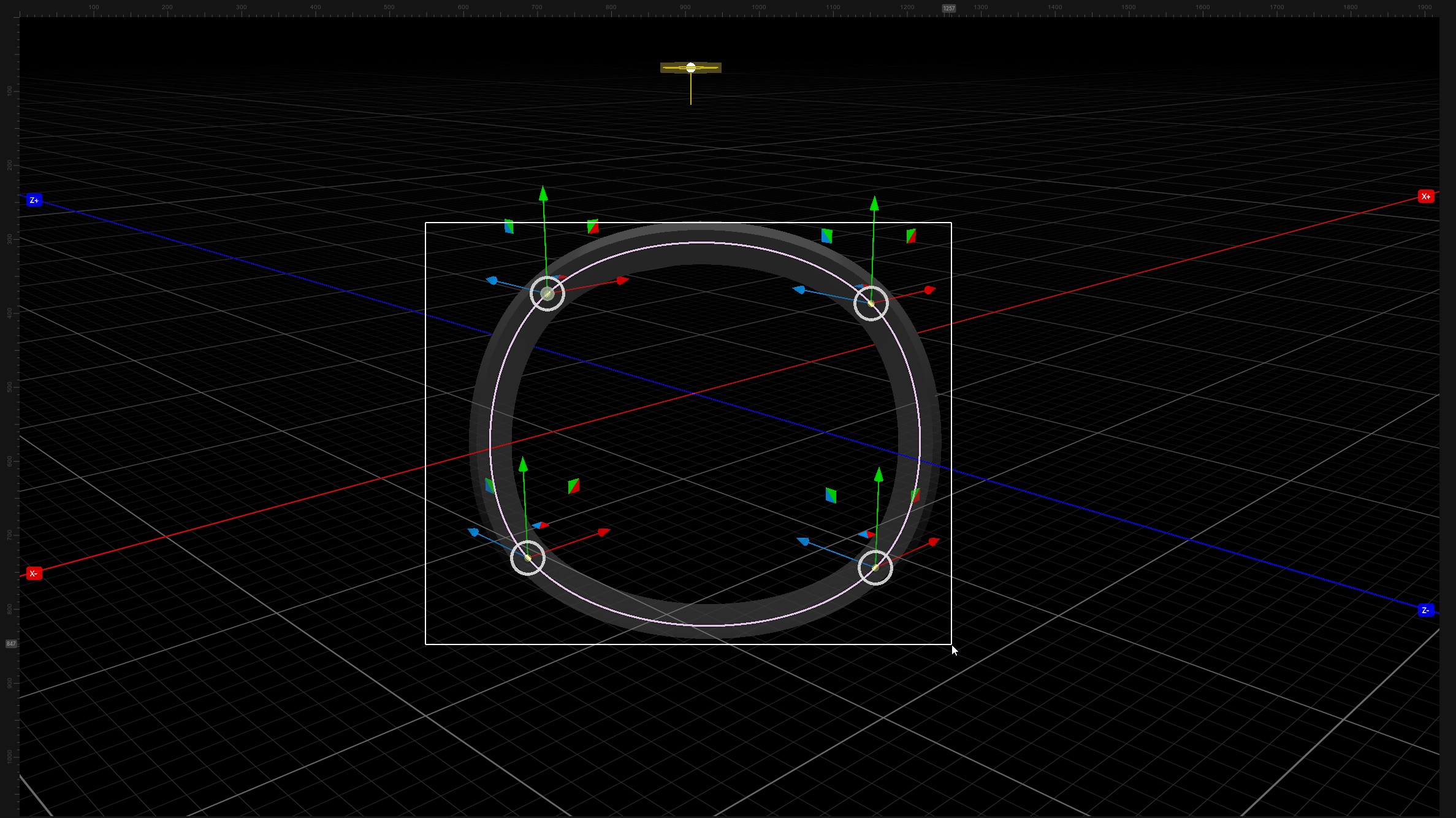
You can select multiple points in the viewport by:
holding SHIFT down and LMB clicking points to select or deselect points
When ‘Tangent’ ‘Add Point Direction’ mode is selected you can lasso points in the viewport with a LMB click drag
When ‘Tangent’ ‘Add Point Direction’ mode is selected you can add or remove from the selection by holding down SHIFT and lasso points in the viewport with a LMB click drag
When ‘Paint’ “Add Point Direction” mode is selected you can lasso points in the viewport by holding CTRL down then a LMB click drag
When ‘Paint’ ‘Add Point Direction’ mode is selected you can add or remove from the selection by holding down CTRL and SHIFT and lasso points in the viewport with a LMB click drag
Transformation modes supported for multi selection of points are; Translation, XY scaling and placement.
Notes
- Editing selected point properties from the properties panel is not supported for multiple selected points
- Point lassoing is disabled if Free space drag mode is enabled in the viewport top bar
- Manipulating tangent handles is currently not supported in multi selection mode
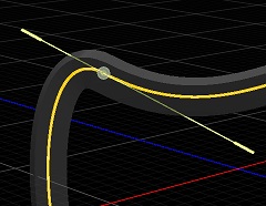
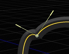
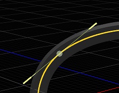
Scaling of tangents can be performed by:
Rotation of tangents can be performed by:
Translation of tangents can be performed by:
All translation interactions support viewport snapping (incremental, viewspace, worldspace)
After Selecting a point in the viewport with a LMB click they can be removed from the spline like so:
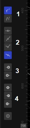
A viewport adjacent ‘Side toolbar’ is also provided for easy access to editing features on a Spline node providing the following functionality:
Spline nodes can be converted to Spline From Nulls nodes so that their underlaying Null derived points can be used for other effects / purposes. In the nodegraph RMB on the Spline node and choose ‘Replace With’, then choose 3d/Spline From Nulls. Effectively you should be able to convert between the two node types but some spline data loss will occur with spline from nulls as they do not have the whole spline point representation, only the outgoing spline tangents.
Splines may also be imported from 3D packages as part of a 3D Scene node.
The following nodes can be used with the Spline node:
Spline Follower to allow geometry or transforms to follow the path of a spline.
Particle Spline Emitter to emit particles from splines.
Spline Deformer to deform 3D objects using splines, and numerous other uses.
Spline Extruder to generate geometry from the spline.
| Parameter | Details |
|---|---|
| Position X | The objects position along the local x-axis. |
| Position Y | The objects position along the local y-axis. |
| Position Z | The objects position along the local z-axis. |
| Rotation Heading | The objects rotation around the local y-axis. |
| Rotation Pitch | The objects rotation around the local x-axis. |
| Rotation Bank | The objects rotation around the local z-axis. |
| Scale X | The objects scale along the local x-axis. |
| Scale Y | The objects scale along the local y-axis. |
| Scale Z | The objects scale along the local z-axis. |
Control the inheritance of the transforms from the parent.
| Parameter | Details |
|---|---|
| Position | Toggle inheritance of the Position from the parent. |
| Rotation | Toggle inheritance of the Rotation from the parent. |
| Scale | Toggle inheritance of the Scale from the parent. |
| World Position Only | Inherit the world position from the parent only, rotation and scale will be ignored. Overrides above properties. |
| Inherit Time | Toggle inheritance of time from the parent. |
These properties control the core behaviours of the node.
| Parameter | Details |
|---|---|
| Isolate In Viewport | When enabled, all other objects in the scene will be hidden and only this node will be rendered. |
| Looping | Control whether the spline loops. |
| Twist Method | Set the method we use to resolve twisting along the spline resulting from interpolation. |
| Add Spline Point To End | Adds a point to the end of the spline. |
| Add Spline Point To Start | Adds a point to the start of the spline. |
| Add Point Direction | Sets the method of adding points and where they will appear. |
| Add to Nearest End Point | If this is enabled and we are in painting mode, we add new points to the closest end of the spline |
| Delete Last Spline Point | deletes the last point on the spline |
| Delete First Spline Point | deletes the first point on the spline |
| Delete Selected Spline Points | deletes the currently selected points |
| Delete All Spline Points | deletes all the points on the spline |
| Normalise Spline Time | Normalises the spline times between 0 and 1. |
| Spline Time Mode |
Controls how the spline is evaluated by spline followers.
|
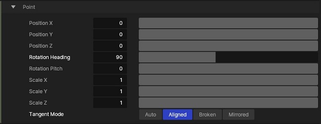
These properties control the individual point attributes.
| Parameter | Details |
|---|---|
| Position X | X position of the point. |
| Position Y | Y position of the point. |
| Position Z | Z position of the point. |
| Rotation Heading | Rotation heading of the point. |
| Rotation Pitch | Rotation Pitch of the point. |
| Scale X | X scale of the point. |
| Scale Y | Y scale of the point. |
| Scale Z | Z scale of the point. |
| Tangent Mode |
Control how the spline tangents are generated for the spline.
|
| Parameter | Details |
|---|---|
| Show Spline | Toggle the spline visualisation mode. |
The properties control the time at which the node is active. See Timeline for editing time segments.
| Parameter | Details |
|---|---|
| Duration |
Control the duration of the node’s time segment.
|
| Node Time | The custom start and end time for the node. |
| Duration (Timecode) | The length of the node’s time segment (in time). |
| Duration (Frames) | The length of the node’s time segment (in frames). |
| Time Segment Enabled | Set whether the node’s time segment is enabled or not in the Timeline. |
| Name | Description | Typical Input |
|---|---|---|
| Transform Modifiers | Apply the transforms of another node to this node. | Null |
| Target Node | Modifiy the rotations of the node to always direct the z axis towards the input. | Null |
| Local Transform Override | Apply the transforms of another node to this node, relative to its parent. | Null |