Revolve Spline
Updated: 4 Jun 2026
Revolve a spline to form a mesh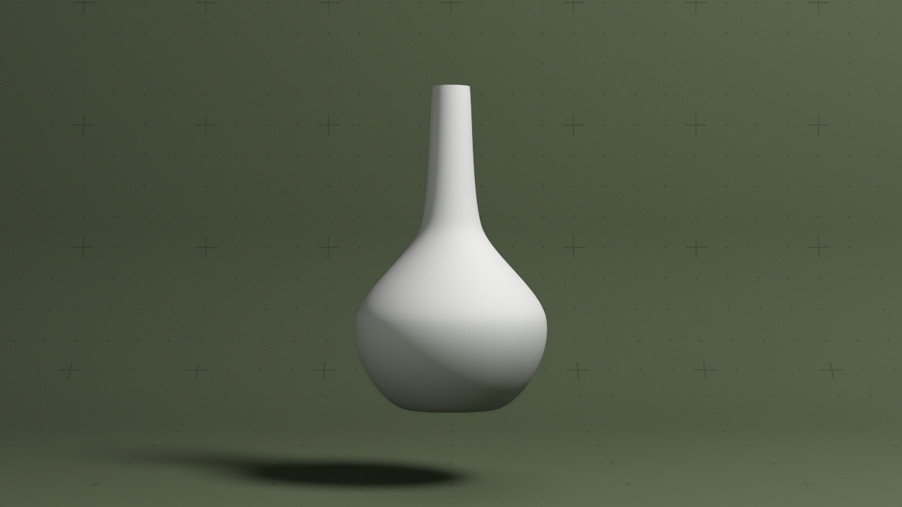
Updated: 4 Jun 2026
Revolve a spline to form a mesh
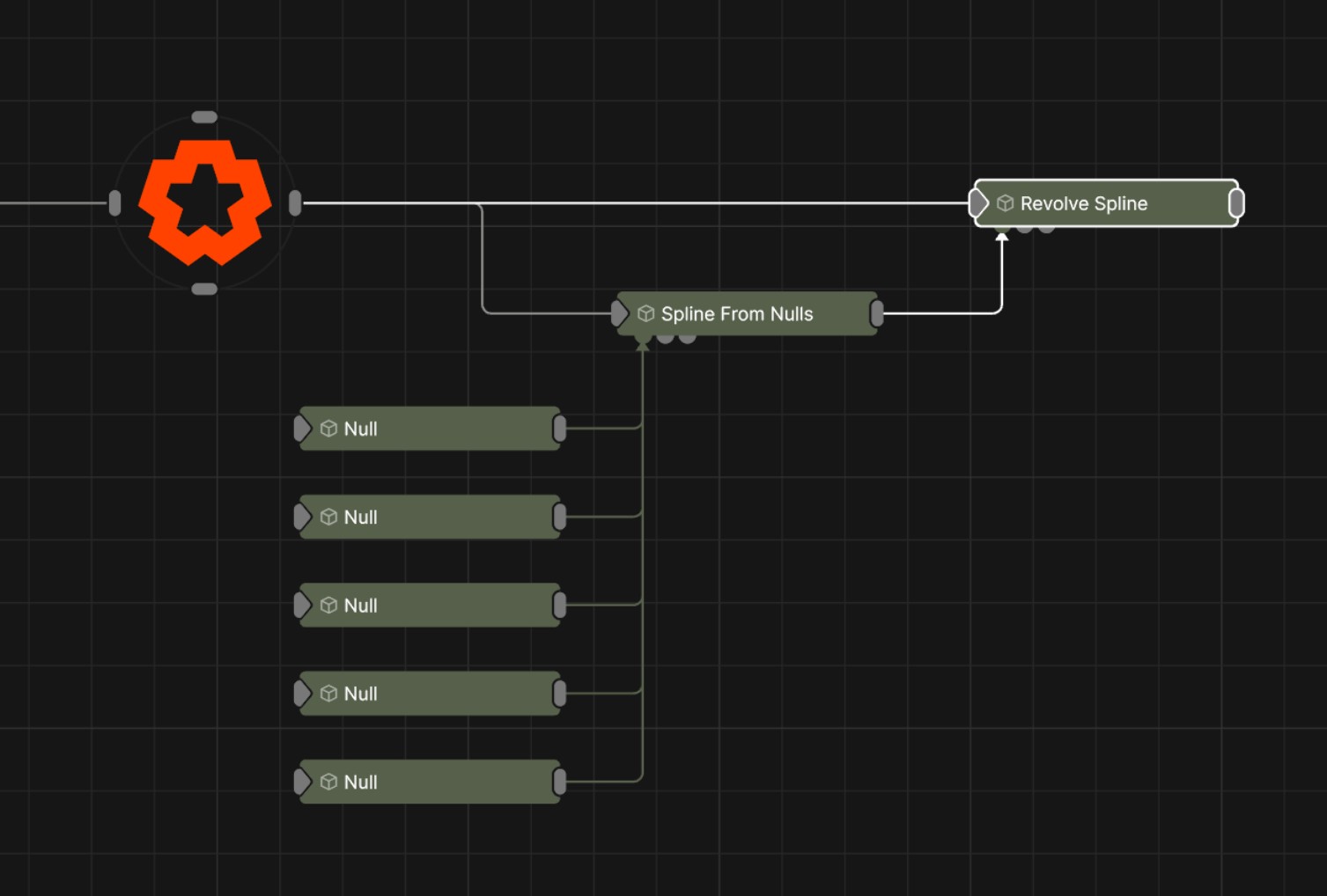
This node generates a mesh from an input spline curve, by following the path the spline would draw when rotated around a central axis. Useful for making vases, bowls, and other objects which are rotationally symmetrical.
A mesh can be used as input if it has the Object To Lines deformer. The Duplicate Splines deformer can also be used to easily draw multiple splines.
This node outputs the normal transformation and translation values, but it also outputs geometry which can be modified with Deformer nodes, or used as a mesh sources for nodes which accept mesh connections, such as the Field Mesh Emitter or the Procedural Mesh.
These properties control the 3D transforms of the node. Transforms will generally be inherited by child nodes, although they can be ignored through the Inherit Transform Channels attributes.
| Parameter | Details |
|---|---|
| Position X | The objects position along the local x-axis. |
| Position Y | The objects position along the local y-axis. |
| Position Z | The objects position along the local z-axis. |
| Rotation Heading | The objects rotation around the local y-axis. |
| Rotation Pitch | The objects rotation around the local x-axis. |
| Rotation Bank | The objects rotation around the local z-axis. |
| Scale X | The objects scale along the local x-axis. |
| Scale Y | The objects scale along the local y-axis. |
| Scale Z | The objects scale along the local z-axis. |
Control the inheritance of the transforms from the parent.
| Parameter | Details |
|---|---|
| Position | Toggle inheritance of the Position from the parent. |
| Rotation | Toggle inheritance of the Rotation from the parent. |
| Scale | Toggle inheritance of the Scale from the parent. |
| World Position Only | Inherit the world position from the parent only, rotation and scale will be ignored. Overrides above properties. |
| Inherit Time | Toggle inheritance of time from the parent. |
These properties control the pivot position the object, the point at which the transforms will be applied around.
| Parameter | Details |
|---|---|
| Pivot Mode | Control where the pivot point is generated for the object. |
| Pivot Point Selection | In custom mode, filter the points shown on the bounding box for placing the pivot. |
| Pivot Position X | In custom mode, directly edit the x position of the pivot. |
| Pivot Position Y | In custom mode, directly edit the y position of the pivot. |
| Pivot Position Z | In custom mode, directly edit the z position of the pivot. |
| Dynamic Update | Control whether the changes to the pivot dynamically update the object. |
These properties control the core behaviours of the node.
| Parameter | Details |
|---|---|
| Isolate In Viewport | When enabled, all other objects in the scene will be hidden and only this node will be rendered. |
| Num Spline Segments | How many subdivisiones are added along the spline length before being revolved. Higher values can improve the smoothness of the curve, but increase the geometry count significantly and therefore can impact performance. |
| Spline Time Min | The start point of the revolved surface along the length of the spline, by a value normalised by the splines length. |
| Spline Time Max | The end point of the revolved surface along the length of the spline, by a value normalised by the splines length. |
| Spline Time Offset | Offset the generated surface before revolution, by a value normalised by the splines length. When used with the Spline Time Min and Spline Time Max, can form a slice which moves along the spline. |
| Num Radial Segments | How many subdivisiones are added around the revolution axis. Higher values can improve the smoothness of the surface, but increase the geometry count significantly and therefore can impact performance. |
| Enable Thickness | When enabled, extrudes the surface along its vertex normals, allowing for a bit of thickness across the revolved surface. |
| Thickness | How thick the surface extrusion should be. Only available when Enable Thickness has been enabled. |
| Use Spline Colours | When enabled, the extruded spline will apply the spline colours from the source spline to the revolved geometries vertex colours. |
These properties control how the geometry is rendered into the scene.
| Parameter | Details |
|---|---|
| Visible | Control whether the node is visible or not to the scene. |
| Seen By Rays | Allow the mesh to be seen by the raytracer. When set to 0, the mesh will still render in camera but will be ignored by any raytracing nodes. |
| Per Object Composite Alpha | Overwrites the alpha channel beneath the object, giving simple effect of transparency. Best used when the mesh won’t overlap with other objects, as other meshes will not be seen through the mesh. |
These properties add options for drawing all the edges of the mesh as lines. Useful for rendering wireframe effects.
| Parameter | Details |
|---|---|
| Lines Visible | Control whether lines are rendered to the scene from the geometry. |
| Lines Alpha | Change the alpha transparency value of the lines, making them appear see-through. |
| Colour | Change the colour value of the lines. |
| Use Vertex Colours | Colour lines based on the vertex colours of the geometry. |
| Thick Lines | Allow the lines to rendered with thickness, for line effects which can be accurately anti-aliased. |
| Hide Back Face Lines | Hide the lines generated from polygon faces facing away from the camera, where only the back faces of geometry can be seen. |
| Lock Width | Lock the line width to be a consistent width regardless of distance from the camera. Only functions with Thick Lines enabled. |
| Thick Line Width | Control the thickness of all the lines. Only functions with Thick Lines enabled. |
| Show Silhouette Lines | Draws lines along the edges of the object relative to the camera. |
| Show Normal Difference Lines | Draw a line along the edges of the mesh, depending on the angle difference between their mutual faces. |
| Show Unshared Lines | Draw lines along all edges of the shape. |
| Show Other Lines | Show all the lines for each edge of the mesh. |
| Unshared Lines Weight | Control the strength of the unshared lines. |
| Silhouette Lines Weight | Control the strength of the silhouette lines. |
| Normal Difference Lines Weight | Control the strength of the lines generated along the normal angles. |
| Other Lines Weight | Control the strength of the lines for each edge in the mesh. |
| Line Normal Difference Angle | Change the threshold angle between two face normals that will generate a line along their common edge. Only functions with Show Normal Lines enabled. |
| Line Normal Fade Sharpness | How much the drawn normal lines will fade away the closer the edge angle is to the Line Normal Difference Angle. |
| Line Depth Bias | Exaggerate the width of the lines based on the distance to the camera. not functional with Lock Width enabled. |
| Line Silhouette Fade Sharpness | How much the drawn silhouette lines will fade away based on the size of the edge angle to the camera. |
Preview the objects material in the viewport.
These properties control how the surface of the generated mesh reacts to light in the scene. See Materials for a breakdown of all these properties individually.
The properties control the time at which the node is active. See Timeline for editing time segments.
| Parameter | Details |
|---|---|
| Duration |
Control the duration of the node’s time segment.
|
| Node Time | The custom start and end time for the node. |
| Duration (Timecode) | The length of the node’s time segment (in time). |
| Duration (Frames) | The length of the node’s time segment (in frames). |
| Time Segment Enabled | Set whether the node’s time segment is enabled or not in the Timeline. |
| Name | Description | Typical Input |
|---|---|---|
| Spline Sources | Spline nodes used to generate the revolve geometry. | Spline |
| Material | Override the default material with a material node. | Materials |
| Displace Images | Image nodes used to displace the geometry. | Gradient |
| Transform Modifiers | Apply the transforms of another node to this node. | Null |
| Target Node | Modifiy the rotations of the node to always direct the z axis towards the input. | Null |
| Local Transform Override | Apply the transforms of another node to this node, relative to its parent. | Null |