3D Primitive
Updated: 28 Jan 2026
Generate a 3D primitive as a mesh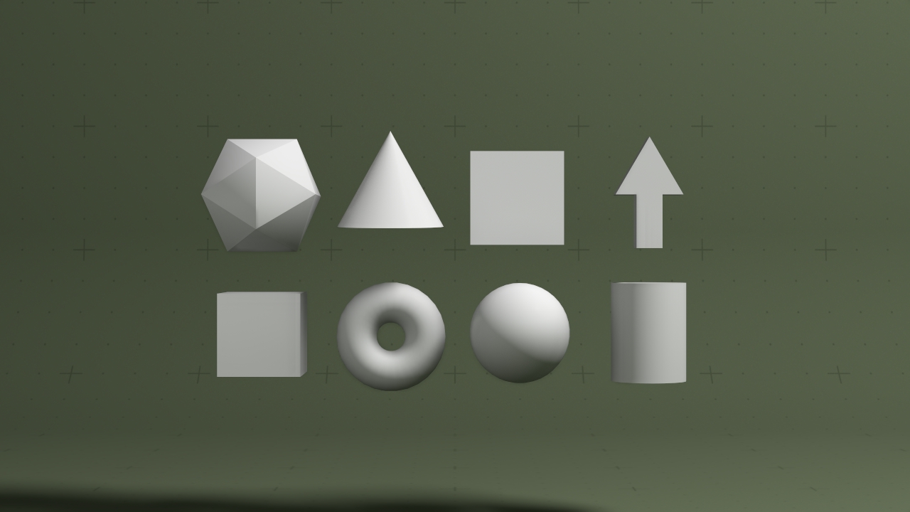
Updated: 28 Jan 2026
Generate a 3D primitive as a mesh
This node generates a 3D primitive mesh, chosen from the meshes Shape Type property. As well as being rendered directly, 3D Primtiives may also be used as an input for various other nodes, including Particle Mesh Emitters, Field Mesh Emitter, Mesh Cloner, and numerous others. A Material Node can also be input to control the meshes material properties.
The 3D Primitive node may be used as a rigid body in a physics system via the Physics Attributes properties. It must be parented under a Rigid Body Root node for physics to be applied.
This node outputs the normal transformation and translation values, but it also outputs geometry which can be modified with Deformer nodes, or used as a mesh sources for nodes which accept mesh connections, such as the Field Mesh Emitter or the Procedural Mesh.
These properties control the 3D transforms of the node. Transforms will generally be inherited by child nodes, although they can be ignored through the Inherit Transform Channels attributes.
| Parameter | Details |
|---|---|
| Position X | The objects position along the local x-axis. |
| Position Y | The objects position along the local y-axis. |
| Position Z | The objects position along the local z-axis. |
| Rotation Heading | The objects rotation around the local y-axis. |
| Rotation Pitch | The objects rotation around the local x-axis. |
| Rotation Bank | The objects rotation around the local z-axis. |
| Scale X | The objects scale along the local x-axis. |
| Scale Y | The objects scale along the local y-axis. |
| Scale Z | The objects scale along the local z-axis. |
Control the inheritance of the transforms from the parent.
| Parameter | Details |
|---|---|
| Position | Toggle inheritance of the Position from the parent. |
| Rotation | Toggle inheritance of the Rotation from the parent. |
| Scale | Toggle inheritance of the Scale from the parent. |
| World Position Only | Inherit the world position from the parent only, rotation and scale will be ignored. Overrides above properties. |
| Inherit Time | Toggle inheritance of time from the parent. |
These properties control the pivot position the object, the point at which the transforms will be applied around.
| Parameter | Details |
|---|---|
| Pivot Mode | Control where the pivot point is generated for the object. |
| Pivot Point Selection | In custom mode, filter the points shown on the bounding box for placing the pivot. |
| Pivot Position X | In custom mode, directly edit the x position of the pivot. |
| Pivot Position Y | In custom mode, directly edit the y position of the pivot. |
| Pivot Position Z | In custom mode, directly edit the z position of the pivot. |
| Dynamic Update | Control whether the changes to the pivot dynamically update the object. |
These properties control the core behaviours of the node.
| Parameter | Details |
|---|---|
| Isolate In Viewport | When enabled, all other objects in the scene will be hidden and only this node will be rendered. |
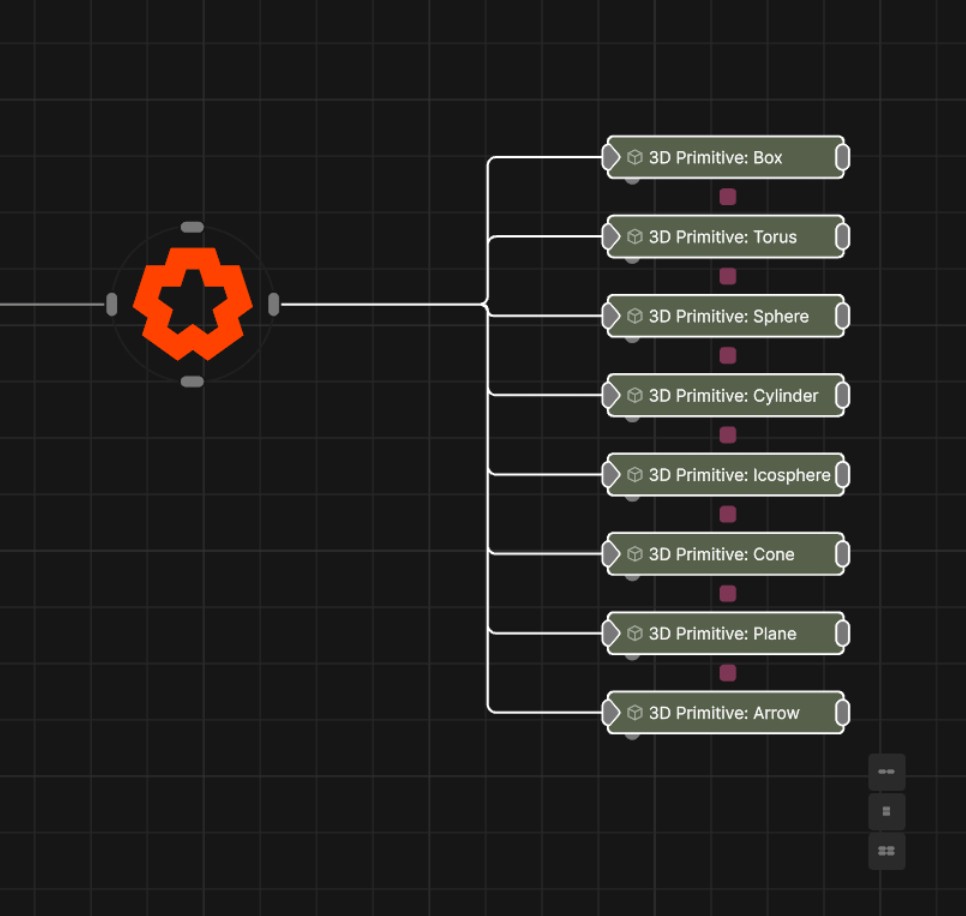
| Shape Type |
Choose which 3D shape is rendered.
|
| Radius | The radius of the primitive, where appropriate. |
| Size Mode |
Choose if the properties define the radius or diameter of the shape.
|
| Subdivisions X | How many subdivisions along the objects X axis. |
| Subdivisions Y | How many subdivisions along the objects Y axis. |
| Origin X |
Set the objects origin point for the X axis.
|
| Origin Y |
Set the objects origin point for the Y axis.
|
| Origin Z |
Set the objects origin point for the Z axis.
|
| Primitive Vertex Count | Shows the original vertex count of the primtiive at generation. |
| Primitive Polygon Count | Shows the original polygon count of the primtiive at generation. |
| Post-Deformer Vertex Count | Shows the current vertex count of the primtiive after all the deformers have been applied. |
| Post-Deformer Polygon Count | Shows the current polygon count of the primtiive after all the deformers have been applied. |
These properties control how the geometry is rendered into the scene.
| Parameter | Details |
|---|---|
| Visible | Control whether the node is visible or not to the scene. |
| Visible To Camera | Is the object visible to the camera. |
| Render As Depth Mask | Renders to depth only, no colour. |
| Visible In Bounces | Is the object calculated in bounce related render properties such as reflections. |
| Casts Shadows | Toggle whether the object can cast shadows. |
| Per Object Composite Alpha | Overwrites the alpha channel beneath the object, giving simple effect of transparency. Best used when the mesh won’t overlap with other objects, as other meshes will not be seen through the mesh. |
These properties control how the UVs of the mesh are transformed when output for the UV camera. Useful for arranging multiple objects to be output for the same UV Camera.
| Parameter | Details |
|---|---|
| UV Scale X | Scale the mesh UV along the X axis. |
| UV Scale Y | Scale the mesh UV along the Y axis. |
| UV Offset X | Move the mesh UV along the X axis. |
| UV Offset Y | Move the mesh UV along the Y axis. |
| Parameter | Details |
|---|---|
| Show Metrics | Displays information about the mesh geometry. |
These properties control the behavious of the object in a Physics System.
| Parameter | Details |
|---|---|
| Static Friction | How much resistance there will be for rigid bodies that are at rest relative to each other to begin moving. |
| Friction | How much other rigid bodies will be able to slide along side this rigid body. When two rigid bodies of different frictions interact, the minimum value is used. |
| Bounciness | How much this rigid body will bounce off of other rigid bodies in the scene. |
| Dynamics Mode |
How the object is used in a physics simulation. Parenting to a Physics Root node node must be done for any physics simulations to occur.
|
| GPU Transform Only | If selected, the transform of the body is maintained on GPU only. This reduces latency and increases performance but means that parenting to the object, e.g. using it to transform lights or emitters, will not work. |
| Rigid Body Convex Hull Mode |
Determines the convex hull shape generation used to wrap around the node’s geometry. only functions if the Convex Hull shape is selected in the Rigid Body Shape.
|
| Collision Radius | The radius of collision shape if applicable. |
| Rigid Body Shape |
The shape of the rigid body used for physics simulation. Often times, a simpler approximation of a mesh can be used for significantly improved performance.
|
| Collision Mode |
Mode for calculating collision if applicable.
|
| Bake Physics Transforms | Bake physics transforms so they are no longer dynamic, but reliably playback and are more performant. |
| Baked Transform | Select the baked physics transform. |
These properties add options for drawing all the edges of the mesh as lines. Useful for rendering wireframe effects.
| Parameter | Details |
|---|---|
| Lines Visible | Control whether lines are rendered to the scene from the geometry. |
| Lines Alpha | Change the alpha transparency value of the lines, making them appear see-through. |
| Colour | Change the colour value of the lines. |
| Use Vertex Colours | Colour lines based on the vertex colours of the geometry. |
| Blend Mode |
How the object lines blends with the rest of the content in a 3d scene. See Blend Modes for details.
|
| Thick Lines | Allow the lines to rendered with thickness, for line effects which can be accurately anti-aliased. |
| Hide Back Face Lines | Hide the lines generated from polygon faces facing away from the camera, where only the back faces of geometry can be seen. |
| Lock Width | Lock the line width to be a consistent width regardless of distance from the camera. Only functions with Thick Lines enabled. |
| Thick Line Width | Control the thickness of all the lines. Only functions with Thick Lines enabled. |
| Show Silhouette Lines | Draws lines along the edges of the object relative to the camera. |
| Show Normal Difference Lines | Draw a line along the edges of the mesh, depending on the angle difference between their mutual faces. |
| Show Unshared Lines | Draw lines along all edges of the shape. |
| Show Other Lines | Show all the lines for each edge of the mesh. |
| Unshared Lines Weight | Control the strength of the unshared lines. |
| Silhouette Lines Weight | Control the strength of the silhouette lines. |
| Normal Difference Lines Weight | Control the strength of the lines generated along the normal angles. |
| Other Lines Weight | Control the strength of the lines for each edge in the mesh. |
| Line Normal Difference Angle | Change the threshold angle between two face normals that will generate a line along their common edge. Only functions with Show Normal Lines enabled. |
| Line Normal Fade Sharpness | How much the drawn normal lines will fade away the closer the edge angle is to the Line Normal Difference Angle. |
| Line Depth Bias | Exaggerate the width of the lines based on the distance to the camera. not functional with Lock Width enabled. |
| Line Silhouette Fade Sharpness | How much the drawn silhouette lines will fade away based on the size of the edge angle to the camera. |
Preview the objects material in the viewport.
These properties control how the surface of the generated mesh reacts to light in the scene. See Materials for a breakdown of all these properties individually.
The properties control the time at which the node is active. See Timeline for editing time segments.
| Parameter | Details |
|---|---|
| Duration |
Control the duration of the node’s time segment.
|
| Node Time | The custom start and end time for the node. |
| Duration (Timecode) | The length of the node’s time segment (in time). |
| Duration (Frames) | The length of the node’s time segment (in frames). |
| Time Segment Enabled | Set whether the node’s time segment is enabled or not in the Timeline. |
| Name | Description | Typical Input |
|---|---|---|
| Material | Override the default material with a material node. | Materials |
| Transform Modifiers | Apply the transforms of another node to this node. | Null |
| Target Node | Modifiy the rotations of the node to always direct the z axis towards the input. | Null |
| Local Transform Override | Apply the transforms of another node to this node, relative to its parent. | Null |